
arduino based remote control for electric door

The replacement remote control system for the electric garage door consists of a transmitter and a receiver, designed to communicate wirelessly. The transmitter is equipped with a microcontroller that generates a unique code each time the button is pressed, ensuring secure access to the garage. This code is transmitted via radio frequency (RF) to the receiver unit, which is connected to the garage door opener.
The receiver includes a decoder circuit that interprets the incoming RF signals. When the correct code is received, the decoder activates a relay that controls the garage door motor. The circuit is powered by a regulated power supply, which can be sourced from the garage's existing electrical system or from a dedicated battery pack to ensure reliable operation.
To enhance functionality, the system may incorporate additional features such as a rolling code mechanism to prevent unauthorized access, LED indicators to signal transmission status, and a learning function that allows the receiver to accept new transmitter codes. The components are housed in a weather-resistant enclosure to protect against environmental factors, ensuring durability and longevity.
Overall, the design of this replacement remote control system emphasizes reliability, security, and ease of use, providing an effective solution for controlling an electric garage door.I recently built a replacement remote control system for an electric garage door after the old remote had given up for the babillionth time. I`m sure the old one would have been possible to repair once again but it was 35 years old and not much fun.
Old receiver and transmitter Pictures from left to.. 🔗 External reference
Related Circuits
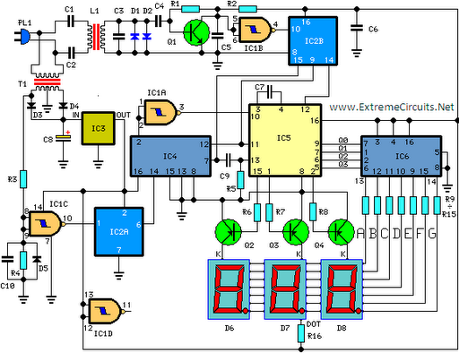
This circuit is designed for precise measurement of temperature in degrees Celsius. It features a transmitter section that converts the output voltage from a temperature sensor, which is proportional to the temperature being measured, into frequency. The resulting frequency...
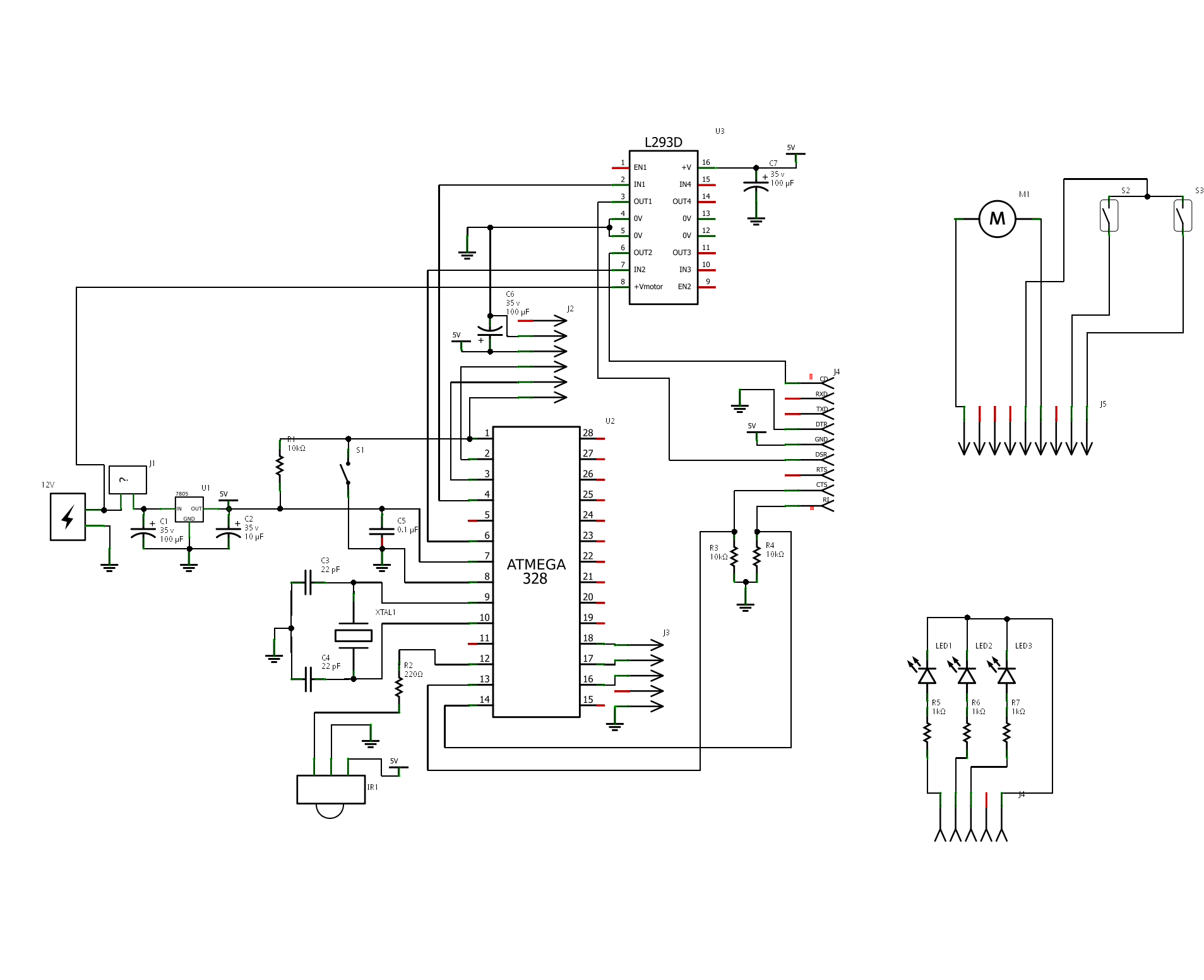
The project is "Motorized Curtain" with Remote control. It is made up of MCU ATMEGA328 with Arduino BootLoader, motor driver L293D (I used L293B with external diodes, because I couldn't find L293D), IR Receiver TSOP 1738, DC Motor from...

Infrared Remote Control Switch Circuit. Remote controls, particularly cordless types, have gained significant popularity in recent times. This document presents a simple infrared remote control switch circuit. The infrared remote control switch circuit utilizes an infrared (IR) transmitter and receiver...
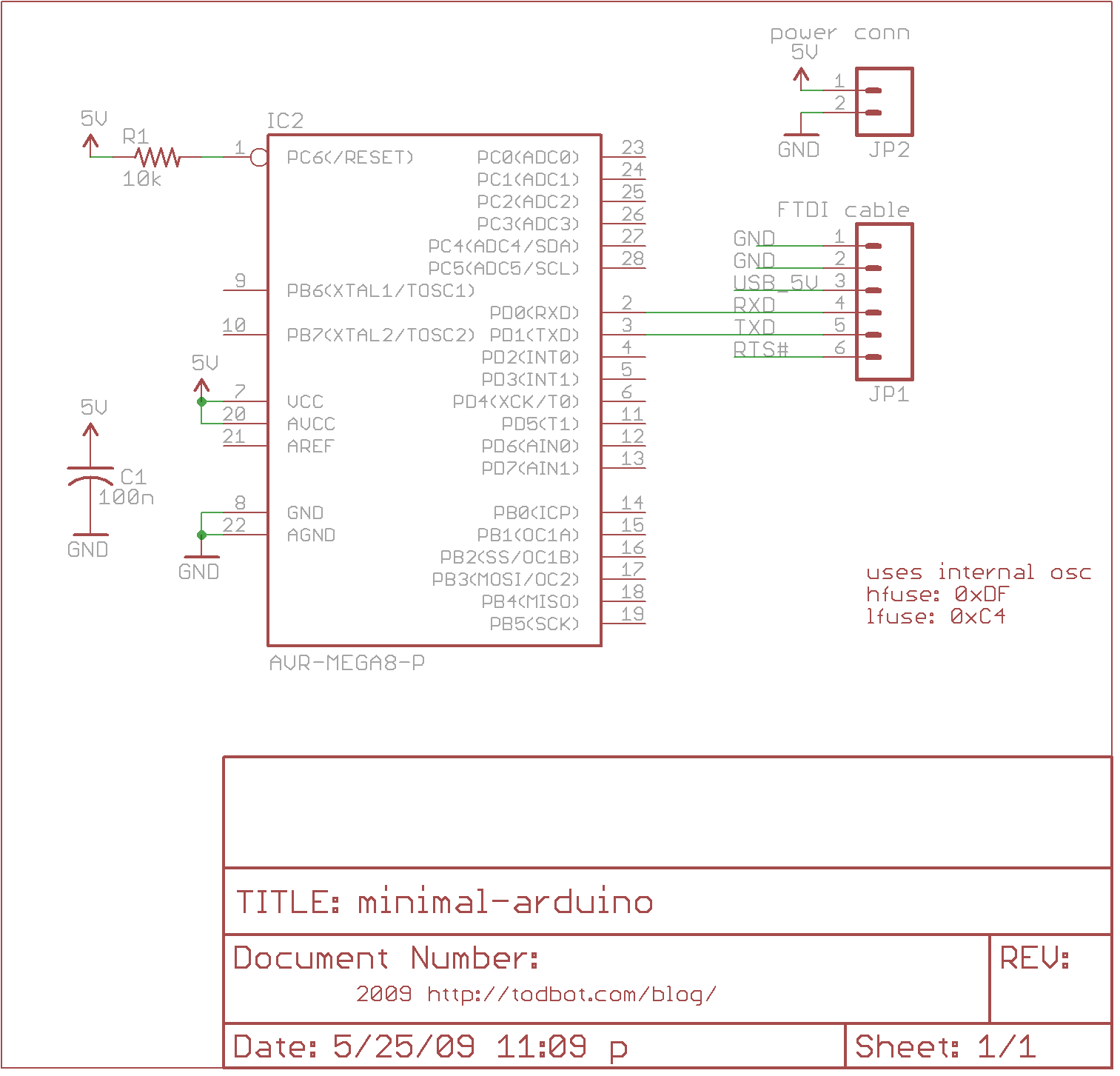
The minimal Arduino circuit is straightforward. It utilizes an internal 8MHz oscillator, similar to the Lilypad Arduino, but does not include a USB-to-serial interface. This functionality must be provided using an FTDI USB-to-serial cable or an older Arduino board....
In certain situations, it is beneficial to enhance the range of available control, and this circuit serves that purpose by receiving the infrared (IR) signal from a remote control and re-transmitting it, potentially around corners or into other rooms....

A simple technique for measuring frequencies across a wide range with acceptable accuracy limits using a PC is presented. This method follows the basic principle of measuring low frequencies, where the period of a complete wave is measured and...