
Auto-advance projector

The monostable is triggered by each positive-going input from the astable. Consequently, the output from the monostable generates a series of short pulses, with the interval between these pulses controlled by switch S2. The output of the monostable, located at pin 11, drives a relay through Ql, which is configured as an emitter-follower buffer stage. The projector is operated via the normally-open contacts of relay Kl. When the output from the monostable becomes positive, the relay contacts close, activating the slide-change mechanism of the projector. The monostable ensures that power is supplied to the relay only momentarily, preventing the projector from operating multiple times in quick succession.
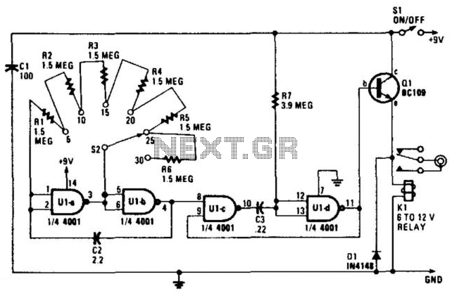
The circuit utilizes a 4001 quad two-input NOR gate, which plays a crucial role in both the astable and monostable configurations. The astable multivibrator is designed to produce a continuous square wave output, where the frequency can be adjusted based on the selected timing resistors. The switch S2 allows the user to choose from six different timing intervals, effectively modifying the resistance in the circuit, which in turn alters the oscillation frequency of the astable multivibrator.
The monostable multivibrator is triggered by the rising edge of the output from the astable, generating a single pulse of a fixed duration for each trigger event. This pulse is defined by the values of R7 and C3; thus, careful selection of these components is essential for achieving the desired timing characteristics. The emitter-follower configuration of transistor Ql ensures that the relay is driven effectively without loading the monostable output, allowing for reliable operation of the projector’s slide-change mechanism.
The relay Kl is critical for interfacing the low-power control signals from the circuit with the higher-power requirements of the projector. The normally-open contacts of the relay provide a simple and effective means to control the projector's operation, ensuring that the slide-change mechanism is activated only when necessary. This design minimizes the risk of unintended multiple slide changes, thereby enhancing the reliability of the projector's operation during presentations.The circuit is built around a 4001 quad two-input NOR gate, it provides switch selectable auto-advance times of 5, 10, 15, 20, 25 or 30 seconds through the remote-control socket of your projector. Ula and Ulb form an astable multivibrator, with its operating frequency dependent on the number of timing resistors switched into the circuit via S2.
The frequency is about one cycle for every five seconds with a single timing resistor, one every ten seconds with two resistors, etc., providing six switched time intervals. The output of the astable at pin 4 of Ulb is fed to the input of a monostable multivibrator, consisting of the second pair of gates, Ulc and Uld.
R7 and C3 are the timing components; they set the length of the (positive) output pulse of the monostable at a little more than half a second. The monostable is triggered by each positive-going input it receives from the astable. The output from the monostable therefore, consists of a series of short pulses, the interval between the pulses being controlled using S2. The output of the monostable (at pin 11) controls a relay by way of Ql, which is configured as an emitter-follower buffer stage.
The projector is controlled via the normally-open contacts of relay Kl. When the output of the monostable goes positive, the relay contacts close, triggering the slide-change mechanism of the projector. The monostable assures that the power to the relay is applied only briefly by the timer, so that multiple operation of the projector is avoided.
Related Circuits
A large mirror is installed on the left wall, enhancing the brightness of the room. However, when watching movies, a dark environment is preferred, as reflections of the film appear in the mirror, which can be distracting. To address...
A 4001 CMOS Quad NOR gate is configured as an astable multivibrator, which drives a simple differentiator and relay driver. Depending on the setting of S2, a delay of 5 to 30 seconds is generated. S2 and R1 through...
The vehicle is a 2005 Pontiac GTO equipped with a 6.0L engine and a 6-speed manual transmission. The factory headlights, which utilize H11 low-beam projectors, have been found to provide inadequate illumination, prompting a retrofit. The plan includes mounting...
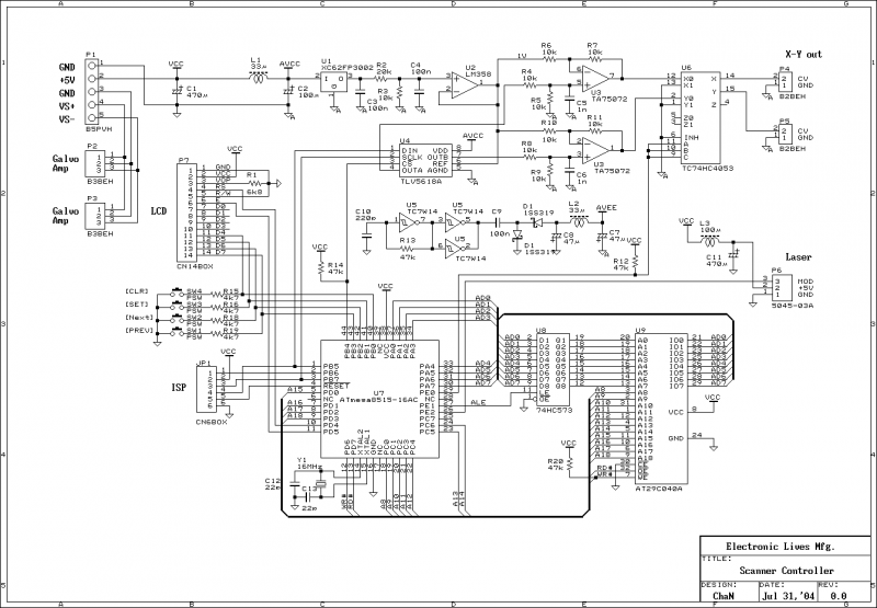
This document outlines the servo amplifier and its circuit diagram. It describes a straightforward operational amplifier circuit that integrates both a power amplifier and a small signal amplifier on the same board. Care must be taken to avoid unintended...
In the production of LCD projectors, the primary factor threatening the lifespan of the LCD screen is the temperature generated by halogen lamps. The multi-function controller designed by this circuit is highly effective for protecting liquid crystal projectors. The...
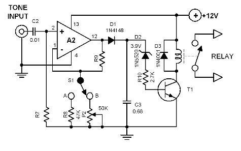
To synchronize audio with projected film, a tone code is utilized. This tone code activates a device that automatically changes the film or slide. A two-channel tape recorder is required for this process, where the normal audio program is...