
Slide Projector Auto Advance

The circuit utilizes a 4001 CMOS Quad NOR gate to create an astable multivibrator, which is a type of oscillator that continuously switches between its high and low states without requiring any external triggering. This configuration results in a square wave output, which can be used to drive subsequent components in the circuit.
In this setup, the output of the astable multivibrator is connected to a simple differentiator circuit. The differentiator serves to convert the square wave signal from the multivibrator into a pulse signal. This pulse signal is then used to activate a relay driver, which is responsible for controlling a relay. The relay can be employed to switch larger loads or perform other tasks as needed.
The delay in the circuit is adjustable and is determined by the setting of switch S2. The time delay can range from 5 to 30 seconds, allowing for versatile timing applications. The resistors R1 through R6 are part of the timing network and can be replaced by a single 10-Mohm potentiometer for ease of adjustment. This modification provides a more straightforward means of setting the desired delay, enhancing the circuit's usability.
The overall design is efficient and straightforward, making it suitable for various applications where a timed relay activation is required. The use of CMOS technology ensures low power consumption, which is beneficial for battery-operated devices. Proper implementation of this circuit can yield reliable performance in timing and control applications. A 4001 CMOS Quad NORgate is set up as an astable multivibrator, which drives a simple differentiator and relay driver. Depending on the setting of S2, a delay of 5 to 30 seconds is generated. S2 and Rl through R6 can be replaced by a single 10-Mohm pot, if desired.
Related Circuits
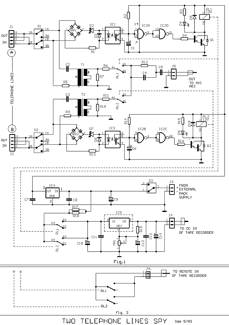
Many times exists the need recording some conversations from a telephone line and this it's relatively easy. If we want however to have the possibility recording from two telephone lines simultaneously in a tape recorder, we needed a circuit...
This is an Auto OFF Light circuit. After the switch is pressed, the bulb remains illuminated for a few seconds. To increase the ON time, a 10k resistor should be used. The Auto OFF Light circuit is designed to provide...
As shown in the generator start battery automatic monitor circuit diagram. The generator start battery automatic monitor circuit is designed to oversee the battery's status during generator operation. This circuit ensures that the battery remains charged and functional, preventing premature...
Automatic gain control. A control circuit that automatically changes the gain (amplification) of a receiver. Automatic Gain Control (AGC) is a crucial circuit used in various electronic devices to maintain a consistent output level despite variations in input signal strength....
Figure 1 consists of a Programmable Unijunction Transistor (PUT) and an automatic interval timer circuit. In this circuit, the PUT serves as the oscillator. The switch S1 is used to toggle between interval timing and automatic timing modes. When...
An emergency light system utilizing white LEDs, which provides several advantages: 1. It is highly bright due to the use of white LEDs. 2. The light activates automatically during a mains power failure and deactivates when mains power is...