
Auto Heat Limiter for Soldering Irons

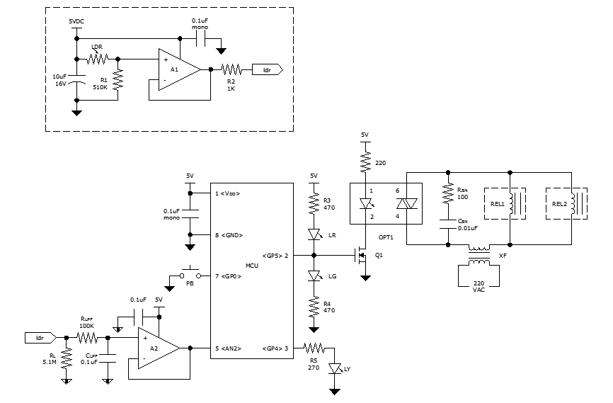
The circuit operates by utilizing a combination of passive and active components to manage the heating of a load connected to the AC mains. The initial detection of the AC voltage drop across R5 provides a stable reference for Q1, which regulates the voltage to a safe level for downstream components. The use of a Zener diode in conjunction with an LED serves a dual purpose: voltage regulation and visual indication of circuit activity.
The relay, activated by the charging of C3, allows for the full AC waveform to energize the load initially, ensuring efficient heating. The design includes a timed delay feature that prevents overheating by limiting the duration of full AC supply after the initial heating phase. The gradual discharge of C3 through resistors R2 and R3 offers a controlled timing mechanism, ensuring that the load does not receive excessive power if the circuit is reactivated too soon.
The circuit's safety features are paramount, particularly the design choice to maintain the load in a safe state should any component fail. The inclusion of D5 as a protective diode ensures that the load is never exposed to an uncontrolled AC supply, safeguarding against potential damage or hazards.
Overall, the circuit is designed for reliability and safety, making it suitable for applications where controlled heating is necessary, while also requiring careful handling due to its connection to the AC mains. Proper assembly and adherence to safety guidelines will ensure the effective and safe operation of the device.Certain part of this circuit is directly connected to AC mains. Therefore, do not touch whilst in operation. Disclaimer Please take the greatest of care in handling AC mains supply while constructing this project. If you have no knowledge of mains wiring or unfamiliar with household mains supply, PLEASE DO NOT ATTEMPT CONSTRUCTION.
I take no responsibility in any personal injury or loss of life or properties suffered by any person while undertaking the construction of this project or using the end product by following my instructions. Usually a soldering iron takes a couple of minutes to get adequately heated up to melt the solder, after which the heat generated is much above the requirement and is wasted.
Moreover, excessive heat decreases the life of the bit and the element, causing serious damage to the components. Once the main is switched on, an approximate 15v drop of the positive half cycle across R5 is detected and supplied to Q1 (SL100 or D313), which acts as a voltage regulator.
Zener diode D2 together with diode D3 (yellow LED) stabilizes the emitter voltage of Q1 at 13. 2Vdc, which is then delivered to the relay circuit built around Q2 and C3. Capacitor C3 charges through the base-emitter path of Q2 and causes the relay to actuate, which in turn allows both the half cycles of the AC mains to flow through diode D6 and R5 to the load to heat it up at a normal rate. After a certain lapse of time (about 2 minutes preset) C3 saturates and Q2 stops conducting through the relay, thus switching on series diode D5 to allow only half of the Ac cycle through the load.
After switching off the system, C3 discharges very slowly through R2 and R3. Before C3 gets completely discharged, if the power is switched on again, C3 takes a shorter time to reach the saturation level, thus switching series diode D5 much earlier than the preset time to prevent double heating of the load. However, if the circuit is switched on only after a few seconds of switching off, C3 gets no time to discharge and the relay does not actuate at all.
Moreover, if the relay circuit fails due to any reason and Q2 does not conduct, no harm is done to the load because in that case D5 remains in series with it. Thus the circuit offers complete protection to the load. As stated earlier, the given value of C3 gives a delay of 2 minutes. However, a 1000mfd capacitor can also be used to produce a 4. 5-minute delay. R5 maintains a drop of about 15V across itself. So for use in different load conditions its value changes as shown in Table 1. The whole circuit can be mounted on a PCB and fitted in an adapter case (7. 6cm X 5. 1cm X 6. 4cm) and used as a mains plug. Since R5 gets heated up during the operation, it should be kept well isolated from the other components.
🔗 External reference
Related Circuits
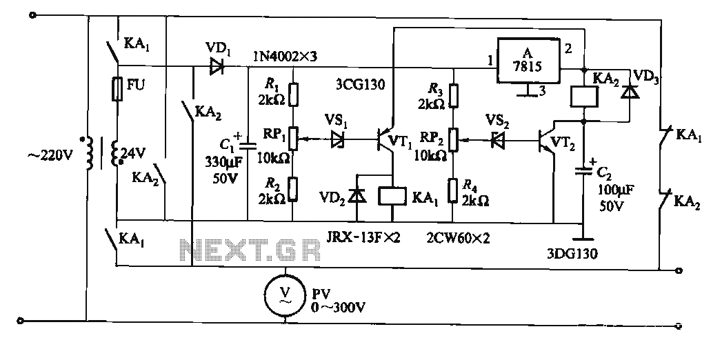
When the input voltage is in the range of 170-260V AC, the output AC voltage falls between 187-231V. The transformer ratio is k = 24/220 = 0.11. If the input voltage drops below 170V, relay KAi activates (adjusted by...
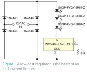
When an application does not require PWM (pulse-width-modulated) dimming or controlled frequency operation, the primary concern may be preventing excessive current that could damage or destroy LEDs. A simple LED current limiter can be created using a common low-dropout...
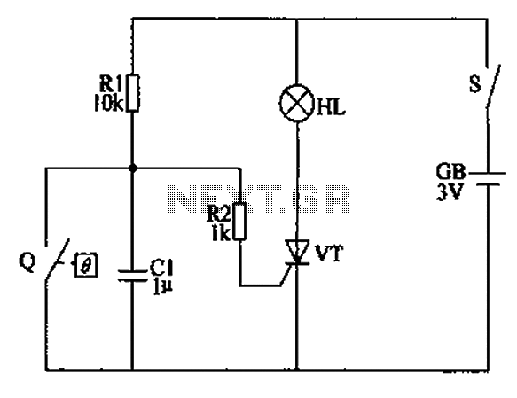
The automatic anti-frost crop controller circuit comprises an electric contact mercury thermometer (Q), a control circuit, ignition devices, and other components. The electric contact mercury thermometer features two platinum electrodes; one acts as a contact electrode inserted at the...
Currently, batteries are becoming increasingly powerful, serving as the sole energy source for portable electronic devices. The rapid evolution of battery technology has prompted manufacturers of electronic equipment to strive for reduced power consumption in their products, enabling them...
To achieve optimal audio reproduction at varying listening levels, it is essential to adjust tone control settings to align with the established characteristics of human auditory perception. The sensitivity of the human ear changes non-linearly across the entire audible...
While discussing an all-linear automatic night light circuit, it was mentioned that an MCU-based Automatic Night Light Controller (ANLC) was being tested. The firmware has been tweaked since then. Recently, the sensor was installed outdoors and connected to control...