
automatic loudness control circuit schematic

The implementation of tone controls in audio systems is crucial for compensating for the ear's frequency response at different sound pressure levels. The Fletcher-Munson curves, which depict equal-loudness contours, indicate that at lower volumes, the human ear is less sensitive to low and high frequencies compared to mid-range frequencies. This phenomenon necessitates the incorporation of adjustable tone controls that can modify the bass, midrange, and treble levels to enhance the listening experience.
A typical audio circuit may include a preamplifier stage, where the audio signal is first processed. Following this, a tone control circuit can be integrated, often utilizing operational amplifiers (op-amps) configured in a feedback arrangement to create bass and treble boost/cut functionality. The control interface may consist of potentiometers allowing users to adjust the gain of specific frequency bands.
For instance, a low-pass filter can be employed to adjust the bass frequencies, while a high-pass filter can manage treble frequencies. The design may also incorporate a band-pass filter for mid-range adjustments. The output of the tone control circuit feeds into the power amplifier stage, which drives the speakers.
In summary, a well-designed tone control circuit is essential for achieving balanced audio reproduction that caters to the non-linear sensitivity of the human ear, ensuring an enhanced listening experience across various volume levels.In order to obtain a good audio reproduction at different listening levels, a different tone-controls setting should be necessary to suit the well known behavior of the human ear. In fact, the human ear sensitivity varies in a non-linear manner through the entire audible frequency band, as shown by Fletcher-Munson curves..
🔗 External reference
Related Circuits
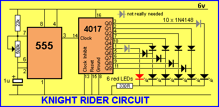
Some simple 555 and flip-flop circuits are being developed to add electronic lighting effects to modernize games. Various circuits are being collected for different game aspects, such as idle states, flipper shots, flower openings, winning shots, etc. A collection...
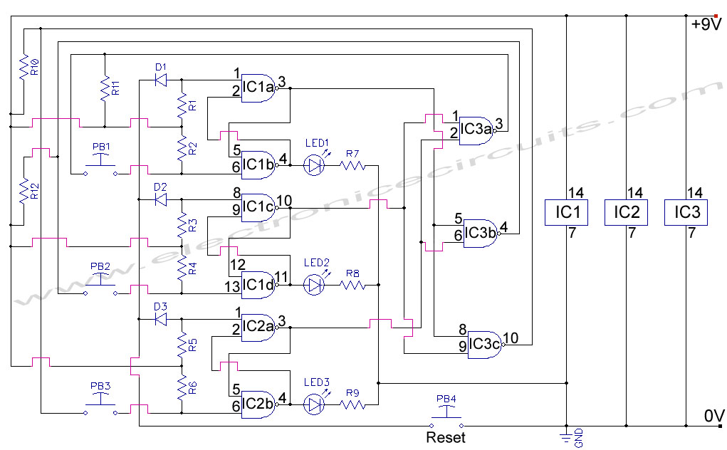
First Response Monitor, Input Selector, Game Circuit. This circuit is utilized for first response applications as it aids in monitoring various responses in games. The First Response Monitor circuit is designed to facilitate real-time monitoring and selection of input signals...
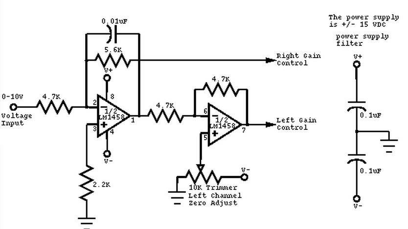
This circuit converts a mono audio signal into a stereo signal that can be panned between the left and right channels using a 0-10V control signal. It is designed for analog synthesizer systems. The circuit operates by taking a single...
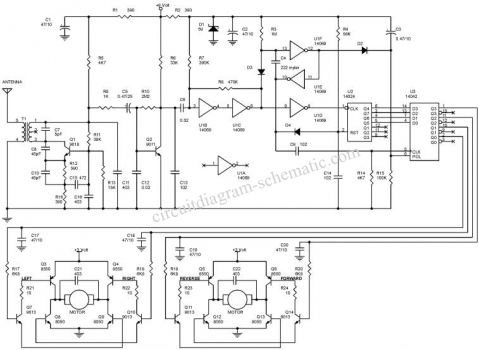
This circuit diagram represents a radio-controlled system, commonly utilized in toy car applications for children. The circuit comprises two main components: the transmitter and the receiver circuits. The transmitter circuit generates radio signals through an oscillator circuit built with...
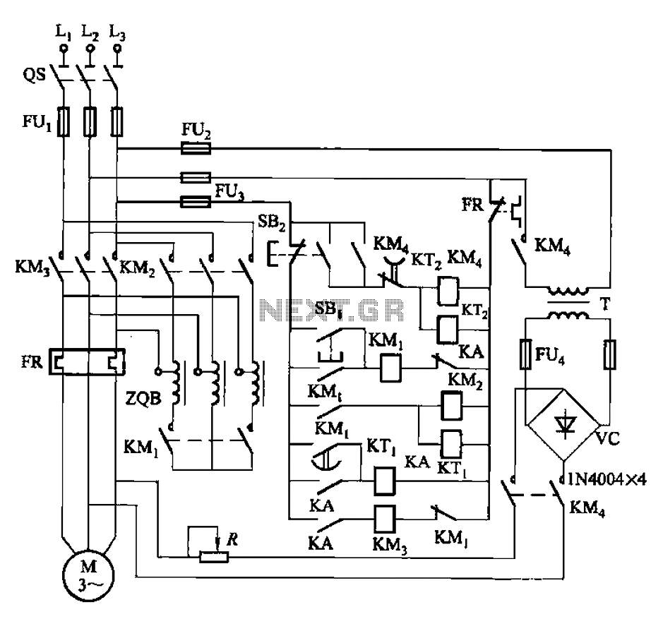
The circuit is illustrated in Figure 3-141. It includes a line autotransformer for voltage starting and dynamic braking. The circuit features a buck start button (SBi) and a stop button (SBz). The buck start-up time is controlled by the...
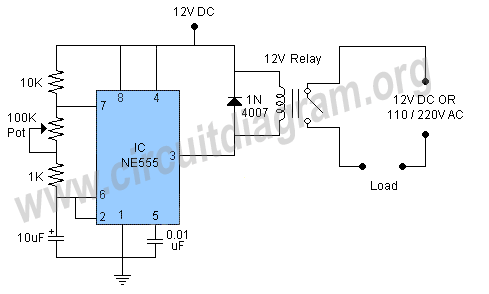
In this circuit, the 555 Timer IC is configured as an astable multivibrator, and a 12-volt relay is operated through pin 3 of the IC. The IC generates continuous pulses at pin 3, which activate and deactivate the relay,...