
Auto OFF Light

The Auto OFF Light circuit is designed to provide a temporary illumination of a bulb after a switch is activated. The operation of the circuit relies on a timing mechanism that allows the bulb to remain lit for a predetermined duration, enhancing user convenience in various applications, such as in hallways or bathrooms.
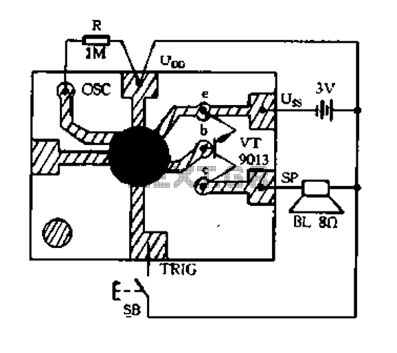
The core components of this circuit typically include a switch, a resistor (10kΩ), a capacitor, and a light bulb. When the switch is pressed, it initiates the charging of the capacitor through the resistor. The time the bulb stays lit is primarily determined by the RC time constant, which is a product of the resistance (R) and capacitance (C) in the circuit.
To increase the ON time, the value of the resistor can be adjusted. A higher resistance, such as 10kΩ, will result in a longer charging time for the capacitor, thus extending the duration the bulb remains illuminated. The formula for the time constant (τ) is given by τ = R × C, where τ is the time in seconds, R is the resistance in ohms, and C is the capacitance in farads.
The circuit may also include a diode to prevent back EMF from damaging components when the bulb is turned off. The light bulb can be of various types, including incandescent or LED, depending on the desired brightness and energy efficiency.
In summary, the Auto OFF Light circuit is a practical design that provides temporary lighting, with the ability to adjust the duration of illumination through component selection, making it suitable for a variety of lighting applications.This is Auto OFF Light circuit. After the switch is pressed, the bulb is kept illuminated for a few seconds. To increase the ON time, The 10k should be. 🔗 External reference
Related Circuits
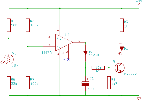
This electronic breadboard circuit for beginners in electronics activates an LED automatically when the ambient light level falls below a specific threshold. This circuit utilizes a light-dependent resistor (LDR) as the primary sensor to detect ambient light levels. The LDR...
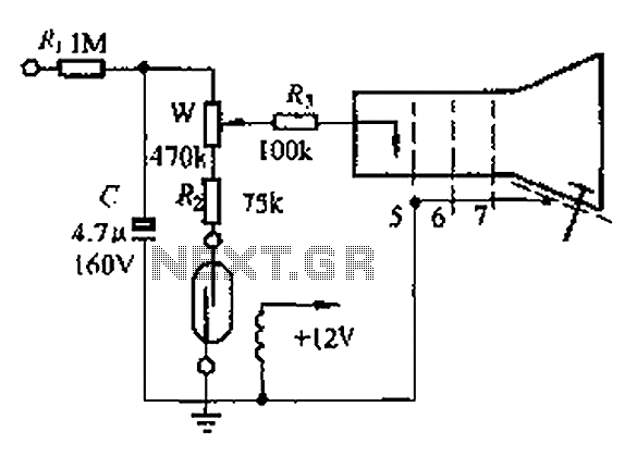
A reed switch is utilized in a TV highlights cancellation circuit. A brightness potentiometer is grounded in series with the reed switch. Under normal operation, the reed contact remains closed, allowing the capacitor C to charge to approximately 160V....
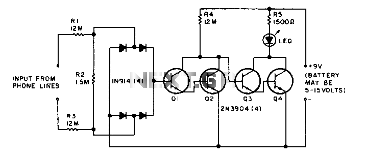
The LED flickers when the phone is ringing or being dialed. It glows steadily when the phone is off the hook. The described circuit involves an LED indicator that serves two primary functions based on the state of the phone....

The cutter is safeguarded by a printed circuit phototransistor designed to prevent accidental activation of the cutter switch during manual feeding. In the event of manual feeding, the automatic paper cutter can be controlled to shut down. A relay...
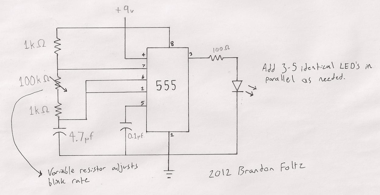
The circuit utilized is a commonly known design. A search for "555 timer LED blinker" will yield numerous schematics that are suitable for this application. The specific schematic presented includes a variable resistor (100K) that allows for user-adjustable blink...
Constantly changing light and sound analog controller circuit 01 The described circuit functions as an analog controller designed to modulate light and sound outputs in a dynamic manner. This circuit typically integrates various electronic components, including resistors, capacitors, transistors, and...