
automatic light

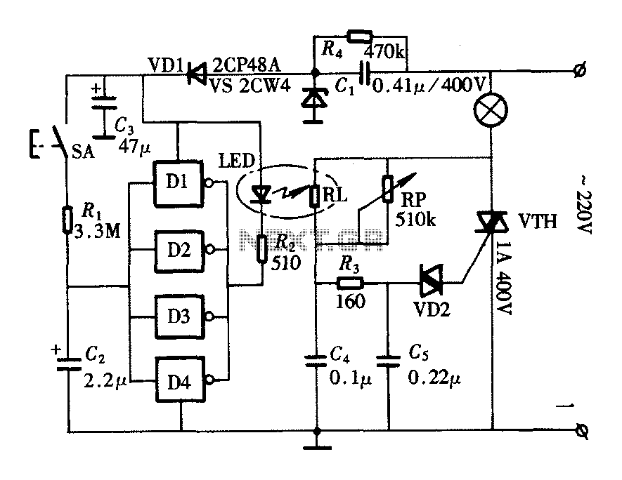
This circuit utilizes a light-dependent resistor (LDR) as the primary sensor to detect ambient light levels. The LDR is a type of resistor whose resistance decreases with increasing incident light intensity. When the light level drops below a predefined threshold, the resistance of the LDR increases, triggering a change in voltage across the circuit.
The circuit typically includes a power supply, such as a battery, connected to a voltage divider formed by the LDR and a fixed resistor. The output from this voltage divider is fed into a comparator or a transistor configured as a switch. When the voltage across the LDR exceeds a certain level, it turns on the transistor, allowing current to flow through the LED, which illuminates.
To enhance the circuit's functionality, a potentiometer may be included in the design, allowing users to adjust the sensitivity of the LDR and set the light threshold at which the LED activates. This feature provides flexibility, enabling users to customize the circuit for various lighting conditions.
Additional components such as a capacitor can be added to smooth out any fluctuations in the light level, preventing the LED from flickering as the light changes. A resistor in series with the LED limits the current to protect it from excessive current that could cause damage.
This simple yet effective circuit serves as an excellent introduction to basic electronics concepts, including light sensing, voltage dividers, and transistor switching, while providing a practical application in ambient light detection.In this electronic breadboard circuit for beginners in electronics, when the ambient light level drops below a certain level, the LED switches on automatically.. 🔗 External reference
Related Circuits
The widespread application of Surface Mount Technology (SMT) in products such as computers, network communications, consumer electronics, and automotive electronics has led to increasingly complex, high-precision, and multifunctional electronic assemblies. Accurate testing techniques can enhance manufacturing efficiency and ensure...
This circuit is a two-wire light level detector, which does not separate the wires for power supply and output signal delivery. It operates using a current loop that performs both functions over a single pair of cables, requiring only...
The provided schematic diagram illustrates an LM741 light/dark sensor circuit, derived from the 741 Op-Amp Tutorial by Tony van Roon. The ECG128/NTE128 transistor can be replaced with any NPN transistor that meets the necessary gain and current specifications for...
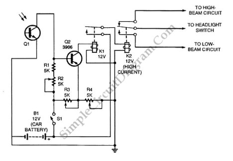
Automatic headlight dimmer circuit diagram for your car's headlight. It ensures safety by providing maximum brightness for the farthest visibility while automatically switching. The automatic headlight dimmer circuit is designed to enhance driving safety by adjusting the brightness of vehicle...
The lighting controller depicted in the figure features a gradual dimming function that prevents sudden brightness changes, which can irritate the human eye and potentially cause damage due to inrush currents. The circuit design includes a six-stage CD4069 inverter...
This circuit gradually switches the internal lights of a car on and off. The delay time can be adjusted by changing the values of the 10k and 4.7M resistors, as well as the capacitor. The circuit operates by utilizing a...