
Automatic bathroom light switch circuit CD4022 composed

The automatic bathroom light switch circuit operates based on the detection of the door's position through a hall effect sensor. This sensor detects magnetic fields and is typically positioned near the door frame, activating the circuit when a magnet, mounted on the door, comes into proximity.
Upon door entry, the hall switch is triggered, sending a signal to the octal counter (CD4022). This counter is designed to count the number of pulses it receives, which corresponds to the door's state (open or closed). The CD4022 is a binary counter that can count up to eight states, providing a reliable method for tracking the door's position.
The pulse divider function of the CD4022 is crucial as it ensures that each opening and closing of the door results in a single pulse being sent to the Triac. The Triac acts as a switch that controls the power to the bathroom light. When the Triac receives a signal from the counter, it allows current to flow to the light fixture, illuminating the bathroom.
For the circuit to function correctly, additional components such as resistors and capacitors may be included to stabilize the operation and prevent false triggering. The design ensures that the light remains on as long as the door is open and turns off automatically when the door is closed again. This automatic control not only enhances convenience but also contributes to energy savings by preventing unnecessary light usage.
Overall, this circuit design effectively combines several electronic components to create a user-friendly and energy-efficient lighting solution for bathroom environments. As shown in FIG bathroom light switch gated automatic way, when someone enters, once the door is opened, the light switch is turned on bright lights. When the out door is opene d once again, switch off the lights off. Circuit as shown in FIG. By the Hall switch circuit, octal counting, pulse divider CD4022 and Triac VTH and other components.
Related Circuits
The circuit receives its input from the zero-crossing detector, which generates a 0-to-1-to-0 pulse to set the R-S flip-flop and activate the ramp circuit (A to Ramp) to initiate the timing ramp ascent. The described circuit operates by utilizing a...
The transmitter described here includes an additional RF power amplifier stage following the oscillator stage, which increases the output power to 200-250 milliwatts. When connected to a properly matched 50-ohm ground plane antenna or a multi-element Yagi antenna, this...

The current design utilizes a stereo decoder integrated circuit (IC) that guarantees a channel separation of 45 dB or more due to its manufacturing process. The intermediate frequency amplifier gain is sufficiently high to achieve a channel separation greater...
One of the unusual features of the out-of-production Programmable Drum Set was its use of touch switches for control. Like most touch switches, these detect the difference in the capacitance of a plate when it is being touched by...
This is a straightforward tester designed to verify the fundamental operations of an infrared remote control unit. It is cost-effective and simple to assemble. The tester utilizes the infrared receiver module TSOP1738. The operation of the remote control is...
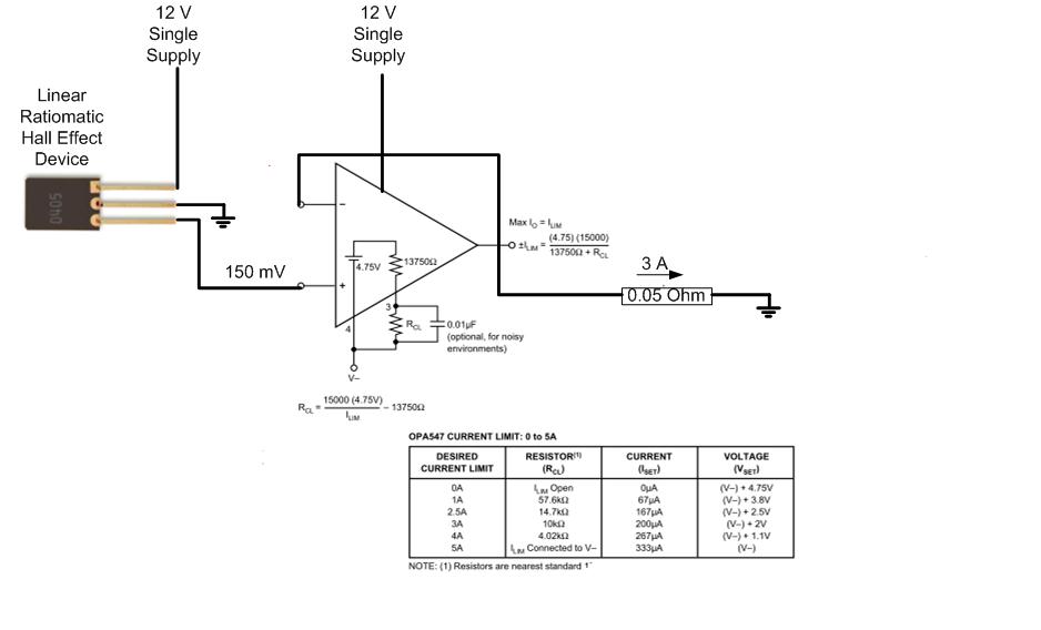
The proposed approach would dissipate (12V)(3A) = 36 watts, which results in significant heat generation in the circuit. This necessitates consideration of two alternatives: 1) Operating the op-amp at a lower supply voltage, if feasible, or 2) Utilizing a...