
220vAC Operated Remote Tester circuit

The infrared remote control tester circuit is an essential tool for troubleshooting and verifying the functionality of remote control devices. The core component, the TSOP1738 infrared receiver module, operates at a carrier frequency of 38 kHz, making it compatible with most consumer remote controls. The module features a photodiode and an amplifier, which work together to receive infrared signals emitted by the remote control.
The circuit configuration typically involves connecting the output of the TSOP1738 to a piezo buzzer. When the infrared signal from the remote control is received, the module demodulates the signal and outputs a digital high level, which activates the buzzer. This audible confirmation allows users to ascertain whether the remote control is functioning correctly.
Power supply requirements for this circuit are minimal, often achievable with a standard 9V battery. Proper decoupling capacitors should be included near the power supply pins of the TSOP1738 to ensure stable operation and to filter out any noise that could affect performance. A resistor may also be included in series with the buzzer to limit the current and protect both the buzzer and the receiver module.
The tester's sensitivity is adjustable by modifying the gain settings in the circuit, which can be accomplished by selecting appropriate resistor values in the feedback loop of the amplifier. This feature allows the tester to be customized for different environments and distances, enhancing its versatility.
Overall, this infrared remote control tester is a valuable tool for electronics enthusiasts and technicians, providing a straightforward method to confirm the operational status of remote control devices with ease and efficiency.Here is a simple tester for checking the basic operations of an infrared remote control unit. It is low-cost and easy to construct. The tester is built around infrared receiver module TSOP1738. Operation of the remote control is acknowledged by a tone from the buzzer. The circuit is sensitive and has a range of approximately five meters. The integrated IR receiver detects, amplifies and demodulates IR signals from the remote control unit. The piezo buzzer connected at its output sounds to indicate the presence of signal from the remote control unit..
🔗 External reference
Related Circuits
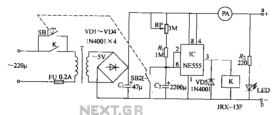
The homemade disinfectant circuit described in this example utilizes an electrolytic salt solution method to produce sodium hypochlorite (NaCl), which can be used for disinfecting living supplies for students. The circuit consists of a power circuit and a timing...
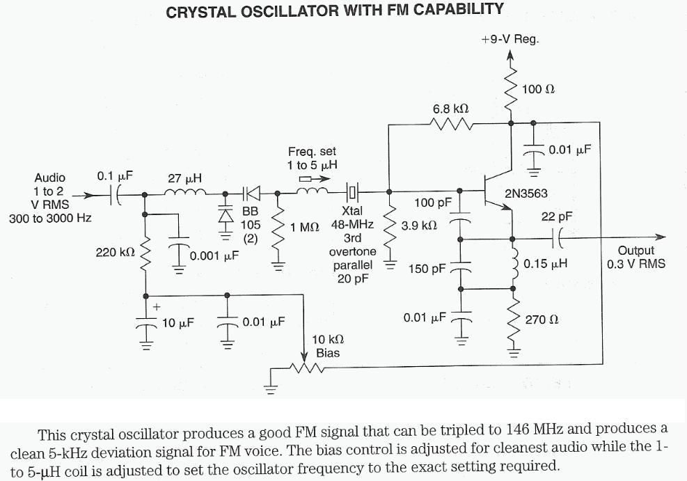
The 7th overtone of 18 MHz (17m) is 144 MHz (2m) directly within the CW region. Icarus is a high-altitude balloon (HAB) project funded by advertising revenue, which has successfully launched numerous balloons that captured impressive photographs. Robert Harrison...

This circuit is capable of generating up to 1 W of audio power to drive a speaker or horn. When the CDS cell is exposed to light, its resistance decreases, activating NOR gate (a). This activation causes gates (a)...
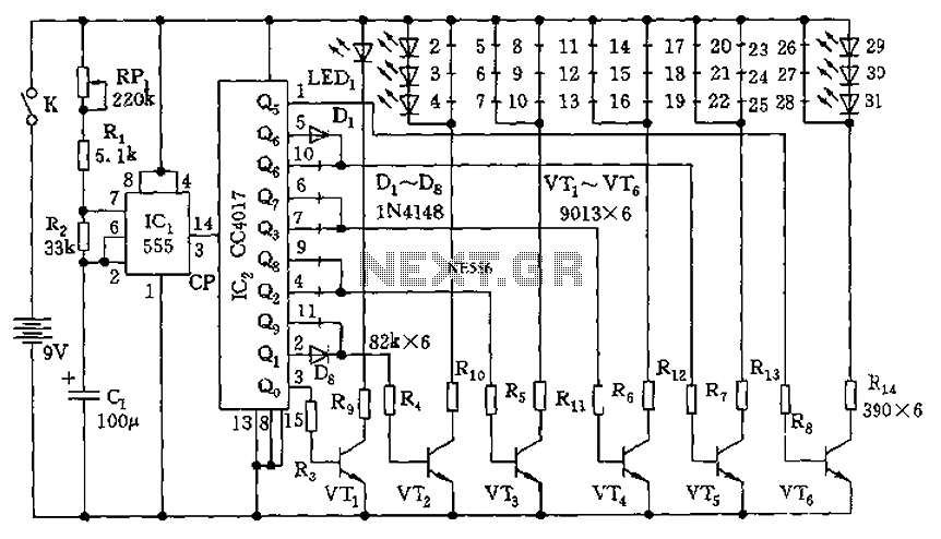
The circuit features a clock pulse generator and a pulse distribution circuit that drives the display circuit. It consists of a 555 timer and resistors RP1, R1, R2, along with capacitor C1, forming an astable multivibrator. The oscillation frequency...
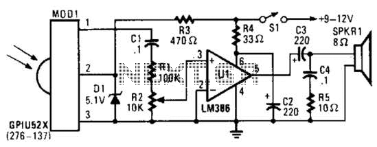
This circuit utilizes an infrared pulse-to-audio converter to assist in troubleshooting infrared remote controls, making it an effective tool for detecting infrared light sources. It employs a photo cell module (Radio Shack P/N 276-137) to detect IR radiation and...

Cable and xDSL modems are increasingly popular, leading to a need for designs that interface with existing telephones at subscriber locations. The subscriber line interface circuit (SLIC) within the modem must ring the phone and provide loop current during...