
battery operated tesla coil

To convert DC to AC for powering a high-voltage transformer in a Tesla coil circuit, an inverter circuit is typically employed. Inverters can be designed using various topologies, including modified sine wave inverters, pure sine wave inverters, or square wave inverters, depending on the application requirements and complexity.
A basic approach involves the use of a push-pull inverter configuration, which utilizes two transistors (such as MOSFETs or BJTs) to alternately switch the DC voltage to the transformer primary winding. The circuit may include a transformer with a center-tapped secondary that provides the necessary alternating current for the high-voltage transformer.
The circuit can be designed as follows:
1. **Power Supply**: The circuit begins with a battery or a battery pack that provides the necessary DC voltage. The voltage level should be suitable for the transistors and the transformer to ensure efficient operation.
2. **Oscillator Circuit**: An oscillator circuit, such as a 555 timer IC or a microcontroller, can be used to generate a square wave signal. This signal drives the base or gate of the transistors, ensuring that they switch on and off alternately.
3. **Transistors**: The selected transistors should be rated for the voltage and current levels involved in the application. They should be configured in a push-pull arrangement, where one transistor conducts while the other is off, and vice versa. This configuration allows the current to flow in alternating directions through the transformer.
4. **Transformer**: The transformer should be designed to step up the voltage to the desired high-voltage level required for the Tesla coil. The turns ratio of the transformer will determine the output voltage based on the input voltage from the inverter circuit.
5. **Filtering and Protection**: Additional components, such as diodes, capacitors, and inductors, may be included for filtering and voltage regulation, as well as protection against back EMF generated by the transformer.
6. **Output Stage**: The output from the transformer can be connected to the Tesla coil, where it will be used to generate high-voltage discharges.
This approach provides a foundational method to achieve the necessary AC voltage from a DC source to effectively power a high-voltage transformer in a Tesla coil application. Proper component selection and circuit design are essential to ensure safety and performance.I`m working on a battery operated tesla coil and im completely stumped on how to convert the dc to ac to power my hv transformer.. 🔗 External reference
Related Circuits
Charge your iPod without connecting it to a computer! Using the USB port on your computer to charge your player's batteries is not always practical. To facilitate the charging of an iPod without the necessity of a computer, a dedicated...
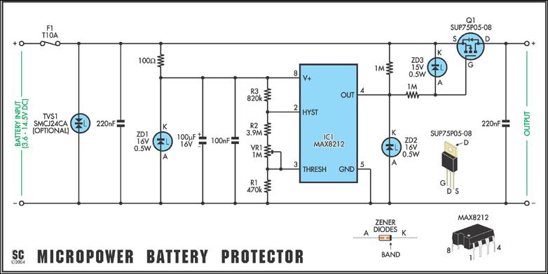
Protect expensive batteries from discharge damage with this mini-sized electronic cutout switch. It consumes minimal power and can be adapted to accommodate a wide range of battery voltages. In May 2002, Silicon Chip introduced the "Battery Guardian," a project...
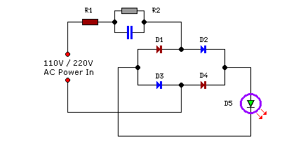
Compact yet highly functional, this is a straightforward and efficient LED circuit designed to operate directly from the AC mains supply, ranging from 100 volts to 230 volts. This LED circuit utilizes a few essential components to achieve efficient...
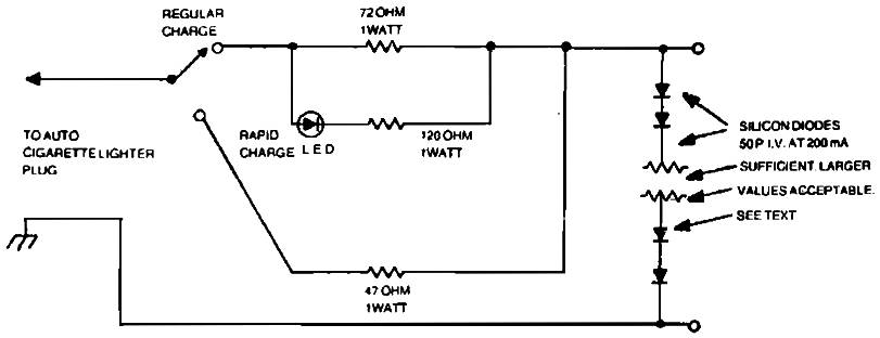
Car charger for NiCd battery packs power supply. This is a car NiCd battery charger circuit that can charge any Ni-Cd battery between 4.8 and 4.4 volts from a classic 12 volts car battery. The charging current is constant...
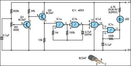
This design integrates power-on and low-battery indication features, capable of operating with any battery voltage up to 15V. It exhibits a very low current drain of 2mA or less. The circuit design incorporates a power-on indicator that activates when the...
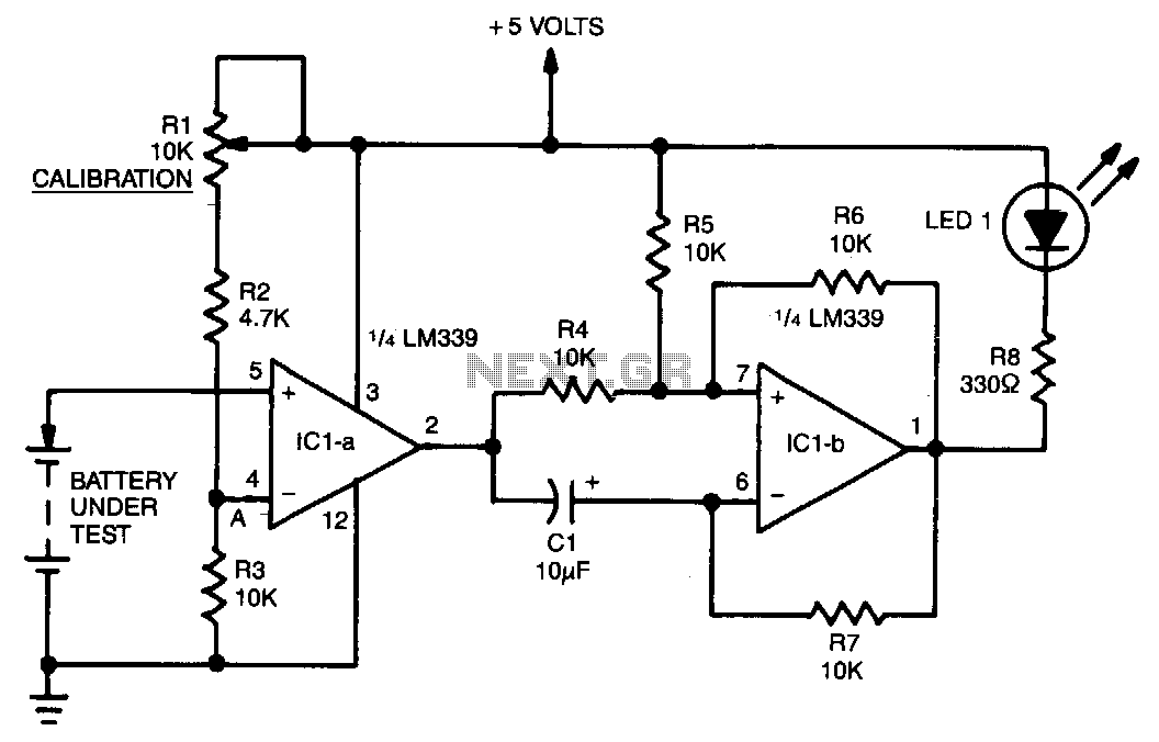
A voltage divider consisting of R1, R2, and R3 is utilized to establish the input reference voltage below which the batteries should be replaced. The reference voltage at point A is adjustable via R1. As illustrated in the diagram,...