
Automatic Car/Vehicle Head Lights Turn Off Circuit

The described circuit utilizes the 555 timer IC in a monostable configuration to achieve the automatic switching function. In this setup, the 555 timer is triggered by a momentary switch, which can be connected to the vehicle's ignition system or a dedicated switch on the dashboard. Upon activation, the timer begins its timing cycle, which is determined by an external resistor-capacitor (RC) network connected to the timing pins of the IC.
The timing period can be adjusted by selecting appropriate resistor and capacitor values. For instance, the time delay (T) can be calculated using the formula T = 1.1 × R × C, where R is the resistance in ohms and C is the capacitance in farads. This flexibility allows the user to set a delay period ranging from a few seconds to several minutes, depending on the application requirements.
Once the preset time elapses, the output pin of the 555 timer transitions from a high state to a low state. This output can be used to control a relay or a transistor, which in turn disconnects the power supply to the vehicle's headlights or lamps. The relay or transistor must be rated appropriately to handle the current required by the vehicle's lighting system.
Additional components may include a diode across the relay coil to prevent back EMF from damaging the 555 timer when the relay is deactivated, as well as capacitors for power supply decoupling to ensure stable operation of the timer. The circuit can be powered from the vehicle's battery, with considerations for voltage levels and current ratings to ensure reliability and safety.
This automatic headlight switch-off circuit enhances vehicle safety by preventing battery drain and ensuring that lights are not left on inadvertently when the vehicle is parked.A circuit that can turn off head lights/lamps of a car/vehicle automatically after a preset time.This light switching circuit is built using 555 timer IC.. 🔗 External reference
Related Circuits
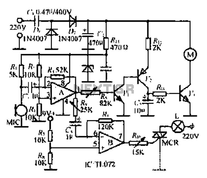
A microphone (MIC) is used to capture sound, which is then converted into a voltage signal. An operational amplifier (op-amp A) acts as a buffer; one output is directed to a motor drive circuit to control the motor's rotation...
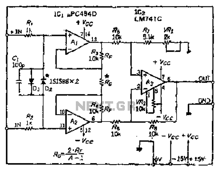
All resistance values are equal, resulting in the Cantonese operational amplifier's gain (A) being equal to 1. However, by selecting smaller resistances, the gain can be adjusted. The circuit can achieve the desired gain through six configurations. Two heavy...
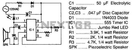
The tester comprises a rectifier circuit and a multivibrator circuit. The alternating current (AC) voltage is half-wave rectified by diode D1 and stored in capacitor C1. Resistor R1 is employed to limit the current through D1 to a safe...
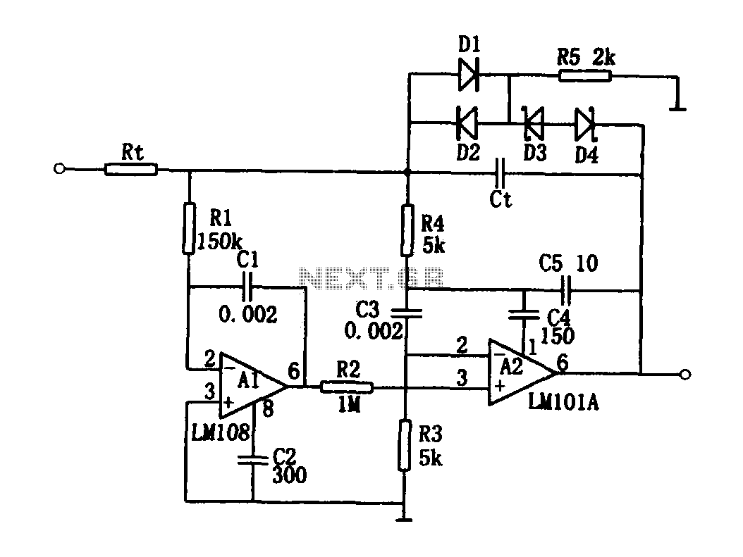
The high-speed integrating circuit is designed with an integration time constant circuit, RtCt, which offers a wide range. When the integrating capacitor Ct is not considered, A2 functions as a positive feedback compensation broadband AC amplifier. The negative feedback...
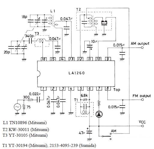
The FM IF MW radio receiver circuit schematic utilizes the LA1260 integrated circuit (IC) for AM and FM radio receiver electronic projects. The LA1260 incorporates numerous functions and features essential for radio receiver applications, including a high signal-to-noise ratio...
One of the simplest methods of metal detecting is through a beat frequency oscillator. The circuit consists of two balanced oscillators: one provides a reference signal, while the other acts as the detector element. The frequency of the reference...