
A Simple Metal Detector Circuit Using Beat Frequency Oscillator (BFO)
")
The beat frequency oscillator (BFO) circuit for metal detection is a straightforward yet effective design that leverages the principles of oscillation and frequency mixing. The circuit typically comprises two oscillators: a stable reference oscillator and a variable detector oscillator. The reference oscillator is designed to produce a consistent frequency output, which serves as a baseline for comparison. In contrast, the detector oscillator's frequency is influenced by external factors, specifically the presence of metallic objects in proximity to its detecting probe.
The reference oscillator can be implemented using various configurations, including LC, RC, or crystal oscillators, depending on the desired frequency stability and component availability. The choice of topology impacts the overall performance of the metal detector, particularly in terms of frequency stability and response time. For the reference oscillator, an RC configuration is often chosen for its simplicity and ease of tuning, with the resistor and capacitor values determining the oscillation frequency.
The detector oscillator, however, is predominantly constructed using an LC topology. This design choice is critical because the inductor's magnetic field interacts with nearby metallic objects, causing a shift in the oscillator's frequency. The inductor in this circuit acts as the sensing element, and its value, along with the associated capacitors, defines the oscillator's operational frequency.
In normal operation, when no metal is detected, both oscillators produce matching frequencies, resulting in a mixer output of zero or minimal frequency. This is indicative of a balanced state where the system is not responding to any metallic interference. Upon the introduction of metal near the inductor, the detector oscillator's frequency changes, leading to a beat frequency output that corresponds to the difference between the two oscillators' frequencies. This output can be further processed to produce an audible tone, allowing the user to identify the presence of metal.
The circuit utilizes a CMOS 4011 NAND gate chip, which is favored for its low power consumption, making it suitable for battery-operated devices. The LM7805L voltage regulator ensures that the circuit receives a stable 5V supply, critical for maintaining the frequency accuracy of the reference oscillator. As battery voltage can fluctuate during usage, the regulator plays a vital role in preventing frequency drift, thereby enhancing the reliability of the metal detection process.
Overall, the beat frequency oscillator metal detector circuit exemplifies an efficient and effective approach to metal detection, combining straightforward electronic components with fundamental principles of oscillation and frequency analysis.One of the simplest method of metal detecting is by beat frequency oscillator. Basically, the circuit consist of two balanced oscillator. One oscillator provides the reference signal, and other oscillator is acting as the detector element. The reference oscillator`s frequency is fix, while the detector oscillator is variable depending on the prese
nce of a metal. The reference oscillator can be constructed using various circuit topology: inductor-capacitor (LC), resistor-capacitor (RC), or even a crystal (quartz) oscillator. While the reference oscillator can be implemented using various circuit topology, the detector oscillator always use inductor-capacitor topology, because the mechanism will be using the magnetic induction property of the detected object, and the inductor component of the detector oscillator will be the detecting probe.
With the absence of a metal near the detector probe (the inductor component of the detector oscillator), the detector oscillator is tuned to have same frequency as the reference oscillator. The output of the detector oscillator and the reference oscillator output is mixed using hetero-dyne mixer circuit, producing a beat frequency output of zero Hz, or a very low frequency if both oscillator is slightly unbalanced.
In the presence of a metal near the detector probe, the detector oscillator will shift it`s frequency, and the mixer output will produce a tone with frequency equal to the difference of the reference and the detector frequency. The figure below shows one of the simple metal detector circuit. You can see the reference circuit is a simple RC circuit, and its frequency is determined by R1-P2-C1.
The detector oscillator is an LC oscillator with the frequency is determined by the L1-C2-C3 values. The NAND gates use CMOS 4011 chip, a low power component that is suitable for this battery-operated circuit. You can see that this chip is supplied by a 5V voltage coming from an LM7805L regulator. You might wonder what the purpose of this regulation is, since the power supply come from a 9V battery and the CMOS gates can handle the voltage of 3-15 Volt.
The main purpose of the regulator is to keep a constant voltage source for the reference oscillator frequency stability, since the frequency is affected by the power supply voltage variation as the battery voltage drops in the long time of usage. 🔗 External reference
Related Circuits
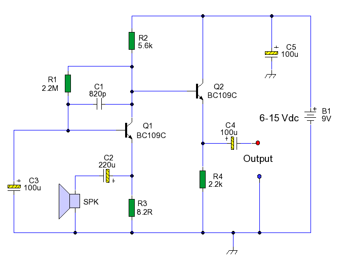
This circuit enables the use of an inexpensive loudspeaker as a microphone. Sound waves that reach the speaker cone create fluctuations in the voice coil. The movement of the voice coil within the speaker's magnetic field generates a small...
This circuit is very basic to build. To open a the lock which is connected to the K1 Load you must press each momentary switch in the correct sequence. The sequence used in this circuit is S1,S2,S3,S4. If any...
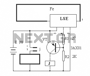
The circuit operation principle of the device illustrated in the figure is as follows: When the barbed wire is intact, the output pin of the LSE is high due to the absence of contact. Consequently, the transistor VT is...
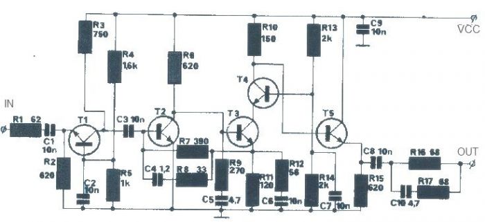
The T1 transistor must be of the BF200 type (or a similar variant), while the other transistors can be of the BF214 type. To achieve high efficiency, the antenna amplifier should be positioned at a short distance from the...
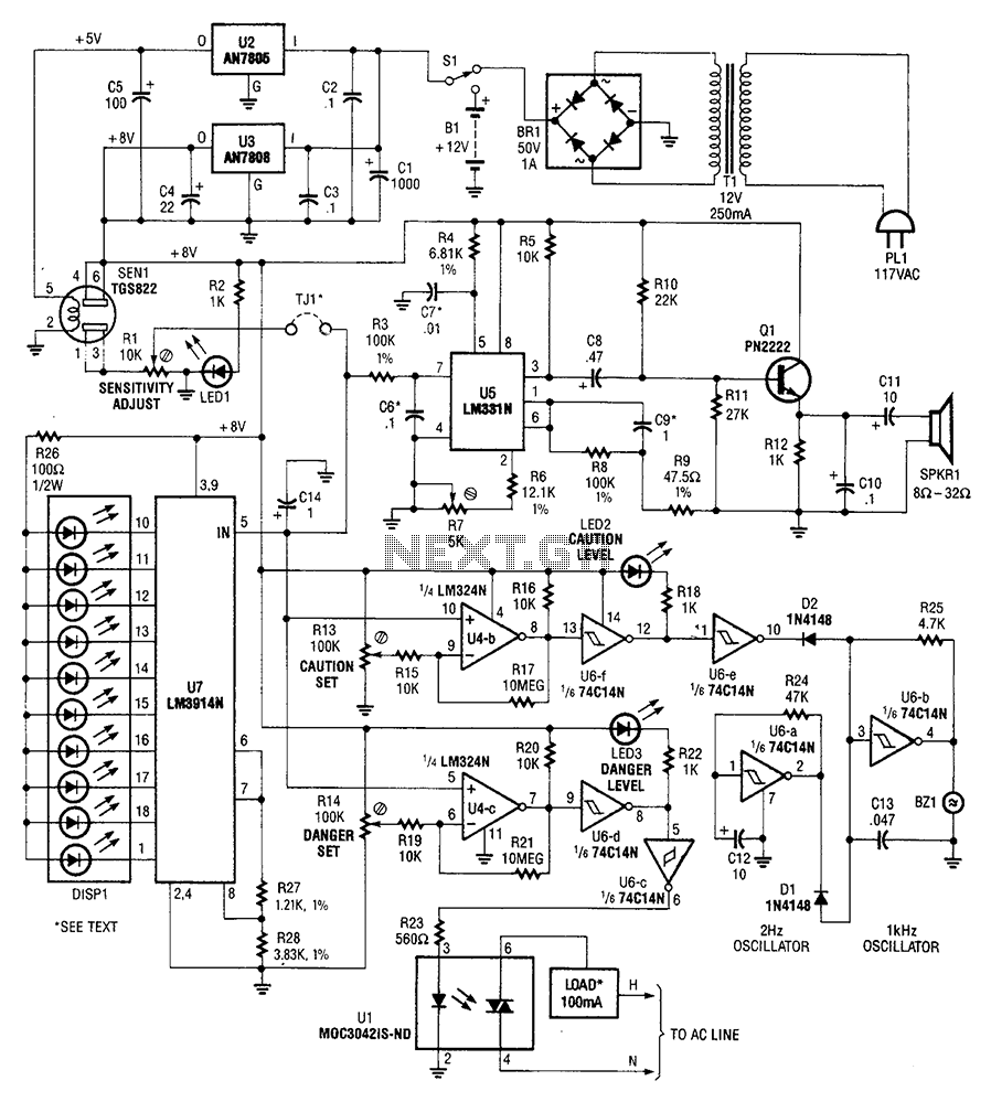
A gas sensor (from Allegro Electronics, Cornwall Bridge, CT06754 Ts GS823) activates in the presence of explosive gas. U5 functions as a voltage-to-frequency converter, with the sensor producing a frequency that is proportional to conductance. The output frequency varies...

This circuit regulates a DC power output and has a wide range of applications. It can be utilized to control the speed of a motor, a pump, a toy train, or the brightness of an LED or lamp. Essentially,...