
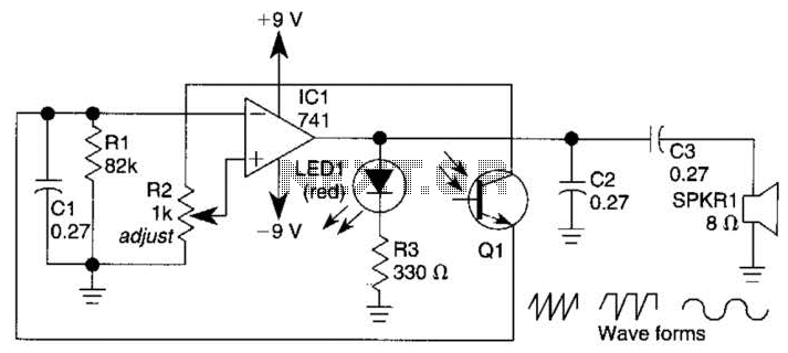
Automatic Dimming Nightlight Circuit

The circuit employs a regulated 6V power supply, which is essential for ensuring consistent voltage levels during operation. The power supply's capacity of 400 mA indicates the maximum current it can deliver, making it suitable for low-power applications. To maintain stable performance, the circuit may incorporate voltage regulation components, such as linear voltage regulators or buck converters, depending on the specific requirements of the project.
Key components may include capacitors for filtering and smoothing the output voltage, ensuring that any ripple is minimized. Additionally, diodes may be included for reverse polarity protection, safeguarding the circuit against incorrect power supply connections.
The circuit layout should be designed to minimize noise and interference, potentially through the use of ground planes and proper routing techniques. Furthermore, the load connected to the power supply should be considered to ensure that it does not exceed the current rating, which could lead to overheating or failure of the power supply.
Overall, this circuit is structured to provide reliable power to the intended application while maintaining efficiency and safety standards. Proper testing and validation should be conducted to confirm the circuit's performance under various operating conditions.This is the circuit that I designed for this project. To power this project, I am using a 6V 400 mA DC power supply. Its open-circuit voltage (no load.. 🔗 External reference
Related Circuits

This example demonstrates a robust design featuring novelty lights that flash in a specific sequence, utilizing a 1-3-2-4 vault chase mode. The circuit includes diodes VD1 to VD4, which form a bridge rectifier, converting AC voltage to a full-wave...
A 555 timer operating in astable mode generates driving pulses, while two 4518 dual BCD (binary coded decimal) counters provide square waves. A TL081 operational amplifier functions as an output buffer-amplifier. Potentiometers R1 and R2 are utilized to control...
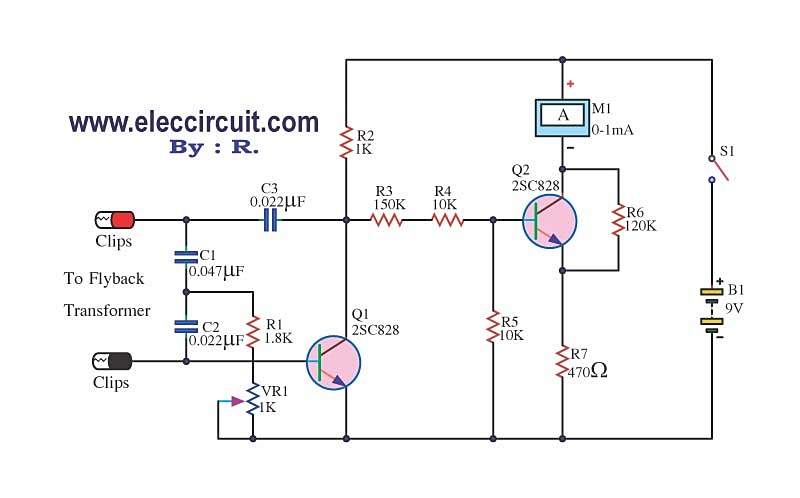
The circuit tests a flyback transformer used in televisions, and it is simple, easy, and inexpensive to construct. A friend who is a TV repairman provided this information. The circuit designed for testing a flyback transformer is essential for diagnosing...

The schematic includes programmable AVRs. For other members of the AVR family or additional programmable ICs compatible with Ponyprog, there is a J1 connector (CON10) that facilitates hardware expansion of the programmer. Additional information about compatible ICs can be...
This current-limiting circuit, illustrated in this example as part of a small bench power supply, could theoretically be utilized alongside any dual-rail current source. The section of the circuit to the left of the diagram restricts the input current...
It is sometimes necessary to monitor a device that generates a relatively short pulse to indicate a change of status. If the duration of the input signal is too short, the RFC-1/B may not have enough time to capture...