
Ponyprog Circuit for ATMEL AVRs

The schematic design highlights the integration of programmable AVR microcontrollers, which serve as the core of the circuit. The J1 connector (CON10) is a critical feature that allows users to expand the programming capabilities of the hardware to accommodate additional ICs beyond those explicitly depicted in the schematic. This flexibility is essential for developers who may want to utilize various microcontrollers from the AVR family or other compatible programmable devices.
The functionality of the JUMP1 jumper is significant in determining the operational mode of the circuit. By connecting or disconnecting the crystal circuitry to the 8-pin AVRs, users can select between using an external crystal oscillator or relying on the internal RC oscillator present in some AVR models. This choice is crucial for optimizing performance based on the specific requirements of the application. It is advisable to consult the JUMP1 configuration table and the datasheet for the specific AVR being used to ensure proper setup.
Furthermore, the JUMP2 jumper plays a vital role in extending the programming capabilities to include members of the AT89Sxxxx family and the AVR's AT90Sxxxx and ATmegaxxx families. This feature enhances the versatility of the programmer, allowing it to support a broader range of microcontrollers, which is particularly beneficial for developers working on diverse projects.
Overall, the schematic serves as a comprehensive guide for integrating and programming various AVR microcontrollers and compatible ICs, providing essential options for customization and flexibility in electronic design.On board the AVRs that can be programmed are those in the schematic. For other members of AVR family or the rest programmable ICs that Ponyprog can program, there is the J1 connector (CON10) which allows expanding the programmer`s hardware. See Ponyprog`s site for other`s ICs Ponyprog circuits. The JUMP1 jumper is there to connect the crystal`s circuitry to the 8- pin AVRs or to disconnect it. Some AVRs have internal RC oscillator and an external XTAL is not allowed or needed. Check the JUMP1`s table and the datasheet for the AVR of your choice for more details. The JUMP2 jumper is there to allow programming a member of the AT89Sxxxx family or the AVR`s AT90Sxxxx & ATmegaxxx family. 🔗 External reference
Related Circuits
The I2C serial bus is a widely used two-wire bus for small-area networks. The I2C Clock and Data lines feature open collector (or drain) outputs for each device on the network, requiring only a single pull-up resistor. This architecture...
Assistance is needed in analyzing a circuit, specifically regarding the frequency cut-off between the bass and treble channels. The potential cut-off frequencies under consideration are 500Hz, 1KHz, or 5KHz. In audio processing circuits, the frequency cut-off point between bass and...
FGDF-3 is a three-phase low-temperature iron plating power commutation control switch and electronic circuit. The KGDF-3 serves as a low-temperature iron plating power supply device, incorporating the characteristics of a single-phase low-temperature iron plating power supply. This design facilitates...

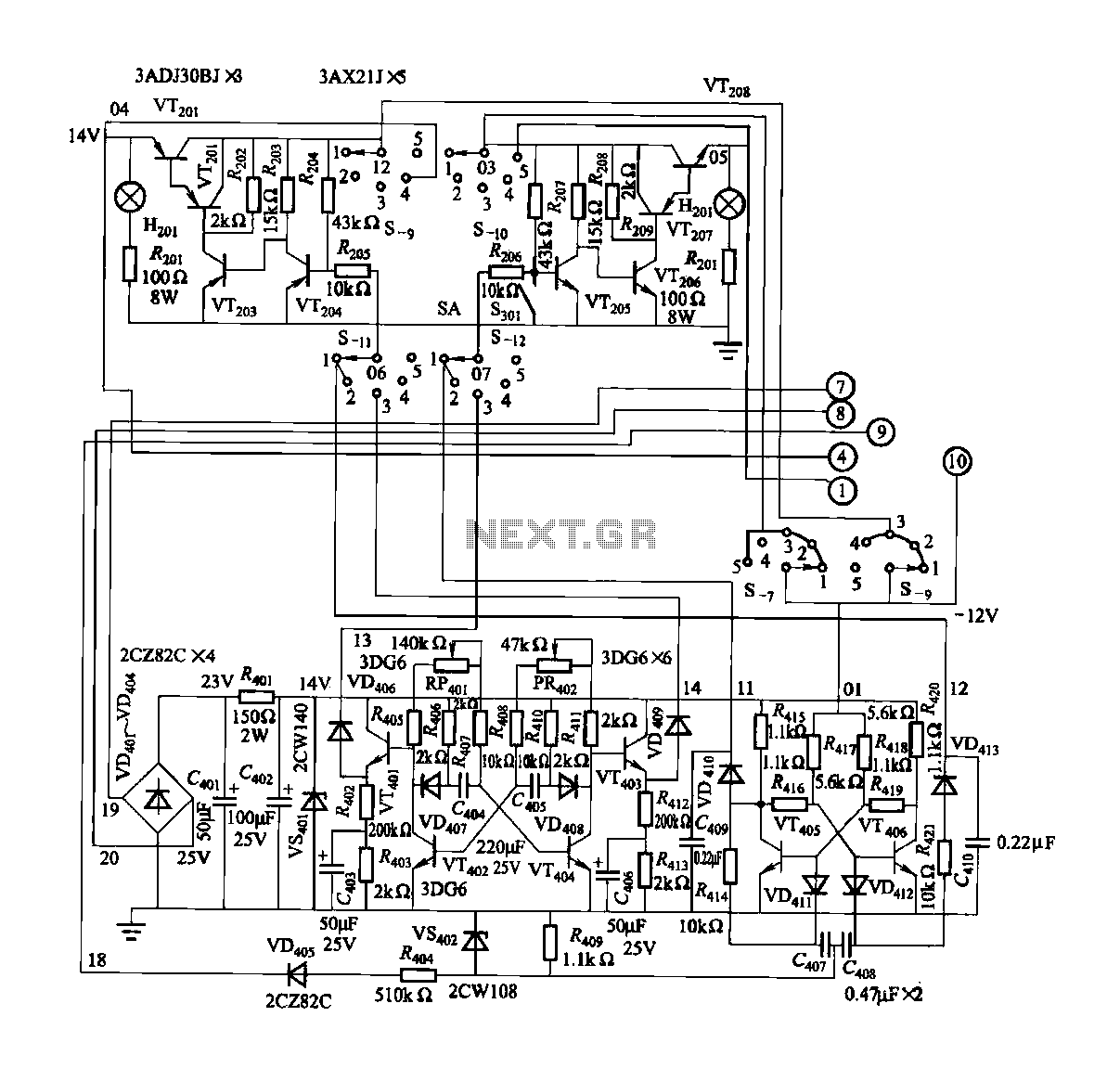
A negative temperature coefficient thermistor is utilized as the temperature sensing element (Rt). The circuit includes a resistor (Ri), a resistor (Rs), a potentiometer (RP), and the thermistor (R) to form a temperature bridge. A differential amplifier is created...
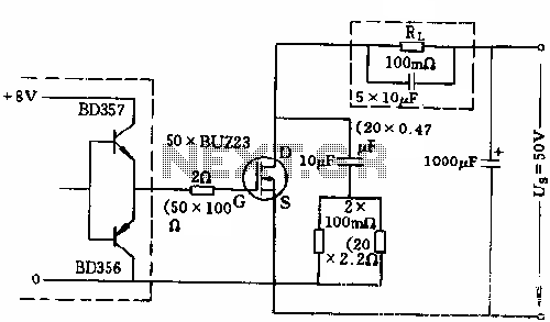
The circuit employs 50 BUZ23 field effect transistors (FETs) arranged in parallel, with a tube blocking voltage of 100V. The control power required is minimal, eliminating the risks associated with second breakdown and the positive temperature coefficient phenomenon in...
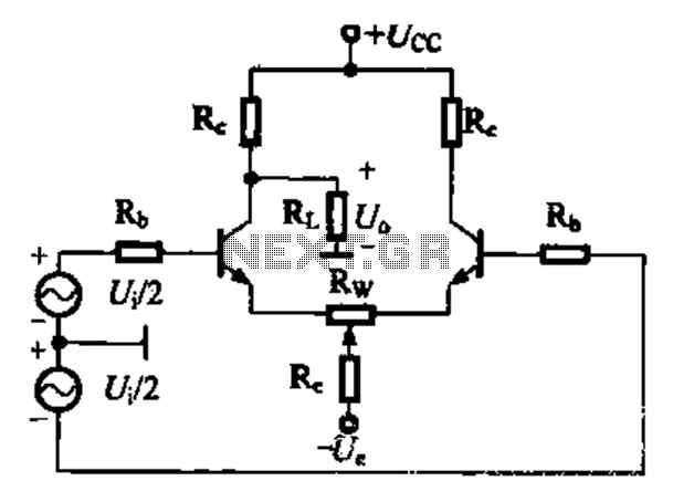
A comparison of four connection methods and features of a differential amplifier circuit is presented. The circuit demonstrates a magnification of a single tube with half the earnings, effectively countering common-mode negative feedback effects. The Common-Mode Rejection Ratio (CMRR)...