
Automatic Dual output Bulb Display

This circuit employs a combination of digital and analog components to achieve a visually appealing sequential lighting effect using ten bulbs. The heart of the system consists of two main integrated circuits: the CD4510 BCD up/down counter (IC2) and the CD4017 decade counter (IC3). The CD4510 counter operates as a BCD counter, allowing it to count from 0 to 9 and then back down to 0, while its output is used to control the sequence of the bulbs.
The oscillator formed by gates N1 and N2 provides a clock signal to IC2, enabling it to increment or decrement based on the logic level present at pin 10. The count direction is determined by this input, allowing for dynamic control over the counting process. The output at pin 7 of IC2 is crucial, as it generates a low pulse upon reaching the ninth count, signaling IC3 to toggle its output state.
The CD4017 decade counter is configured as a toggle flip-flop through the feedback from its Q2 output to the reset pin. This configuration ensures that the output at pin 3 of IC3 alternates between high and low states, effectively creating a binary count that corresponds to the counting operation of IC2. When IC2 counts up and reaches nine, IC3's output transitions, prompting IC2 to count down. This cyclical behavior produces a continuous sequence of lighting effects.
The CD4028 one-of-ten decoder (IC4) translates the BCD output from IC2 into a format suitable for driving the bulbs. Each output from IC4 corresponds to a specific bulb, and as IC2 counts up, the outputs sequentially activate triacs that control the power to the bulbs. This process is mirrored in reverse during the countdown operation, which creates an engaging visual display as the bulbs light up in a sequential pattern both forwards and backwards.
Overall, this circuit exemplifies the integration of digital logic and power control components to create an effective and visually stimulating lighting sequence.This circuit lights up ten bulbs sequentially, first in one direc- tion and then in the opposite direction, thus presenting a nice visual effect. In this circuit, gates N1 and N2 form an oscillator. The output of this oscillator is used as a clock for BCD up/down counter CD4510 (IC2). Depending on the logic state at its pin 10, the counter counts up or down. During count up operation, pin 7 of IC2 outputs an active low pulse on reaching the ninth count. Similarly, during count-down operation, you again get a low-going pulse at pin 7. This terminal count output from pin 7, after inversion by gate N3, is connected to clock pin 14 of decade counter IC3 (CD4017) which is configured here as a toggle flip-flop by returning its Q2 output at pin 4 to reset pin 15.
Thus output at pin 3 of IC3 goes to logic 1 and logic 0 state alternately at each terminal count of IC2. Initially, pin 3 (Q0) of IC3 is high and the counter is in count-up state. On reaching ninth count, pin 3 of IC3 goes low and as a result IC2 starts counting down. When the counter reaches 0 count, Q2 output of IC3 momentarily goes high to reset it, thus taking pin 3 to logic 1 state, and the cycle repeats.
The BCD output of IC2 is connected to 1-of-10 decoder CD4028 (IC4). During count-up operation of IC2, the outputs of IC4 go logic high sequentially from Q0 to Q9 and thus trigger the triacs and lighting bulbs 1 through 10, one after the other. Thereafter, during count-down operation of IC2, the bulbs light in the reverse order, presenting a wonderful visual effect.
🔗 External reference
Related Circuits
This is an easy-to-build yet highly accurate digital voltmeter designed as a panel meter. It can be utilized in DC power supplies or any application requiring precise voltage readings. The circuit uses the CL7107 Analog to Digital Converter (ADC)...
The copyright of this circuit is owned by Smart Kit Electronics. This document discusses improvements and modifications based on the original schematic. It describes a straightforward yet highly accurate and useful digital voltmeter designed as a panel meter, suitable...
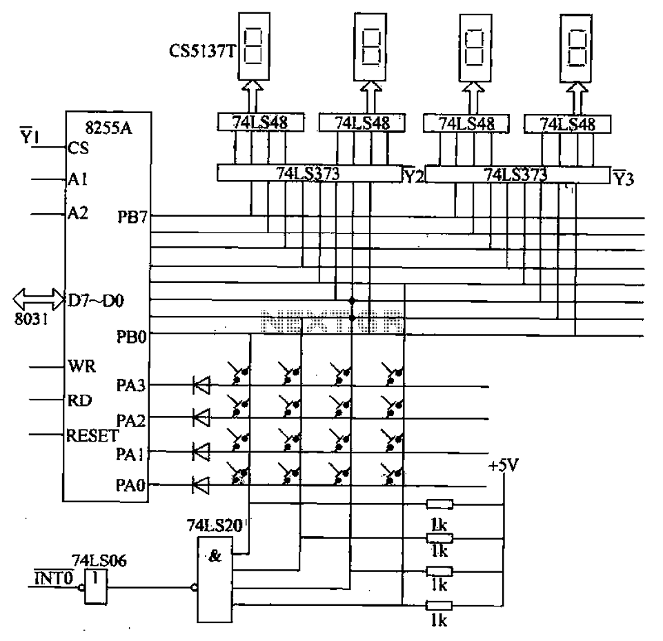
A 4x4 matrix keyboard system is designed for parameter settings, featuring numeric keys from 0 to 9 and function keys labeled A to F. The primary functions of the keyboard include completing parameter settings, selecting display modes, starting automatic...
This circuit is a small digital roulette. It consists of an oscillator IC1, a counter IC2, and transistors Q1-7 that drive the common cathode display DSP1. The power supply typically comes from a 9V battery, but it can also...

The interface circuit is placed between the computer's standard video signal output terminal and the television. It amplifies the standard 1V (Peak-to-Peak) video signal to 3V (Peak-to-Peak). The negative feedback circuit consists of transistors T1 and T2, providing a...
A school operates with a total of eight periods, each lasting 45 minutes, and includes a 30-minute lunch break following the fourth period. A bell is used to signal the start of each class, the end of each period,...