
Automatic Fader Circuit

This circuit operates on the principle of audio signal modulation using a combination of amplification, rectification, and light-dependent resistive feedback. The initial audio signal enters the control channel, where it is processed by diodes D1 and D2. These diodes serve to rectify the audio waveform, converting the alternating current (AC) signal into a direct current (DC) level, which is necessary for controlling the subsequent components in the circuit.
Transistor Q2 is employed to switch LED D3 on and off based on the rectified audio level. The brightness of LED D3 directly influences the resistance of the light-dependent resistor R9. As the audio signal increases, the LED brightness increases, leading to a further decrease in resistance of R9. This feedback mechanism plays a crucial role in dynamically adjusting the audio gain through R11.
The configuration of R11 allows for fine-tuning of the audio gain, making it possible to control how much audio from the input at J2 is allowed to pass through to J3. When R11 is set to a higher value, the output from Q1 increases, allowing more audio to reach J3. Conversely, as R9 shunts audio to ground, it effectively reduces the audio signal at J3, contributing to the fade effect.
The design of this circuit is particularly useful in applications where audio fading is required, such as in audio mixing consoles or sound effect generators. The interaction between the light-dependent resistor and the LED creates a smooth transition in audio levels, enhancing the overall listening experience. In this circuit, audio fed to the control channel is amplified and rectified by Dl and D2. This dc level activates LED D3 via Q2. The light from D3 causes R9, a light-dependent resistor to decrease resistance. As Rll (audio gain) is set higher, more audio is present at the output of Ql. Audio fed into J2 is shunted to ground via R9 and less of this audio appears at J3. Therefore, audio at Jl controls the audio level fed to J3 from J2 andjproduces a fade effect.
Related Circuits
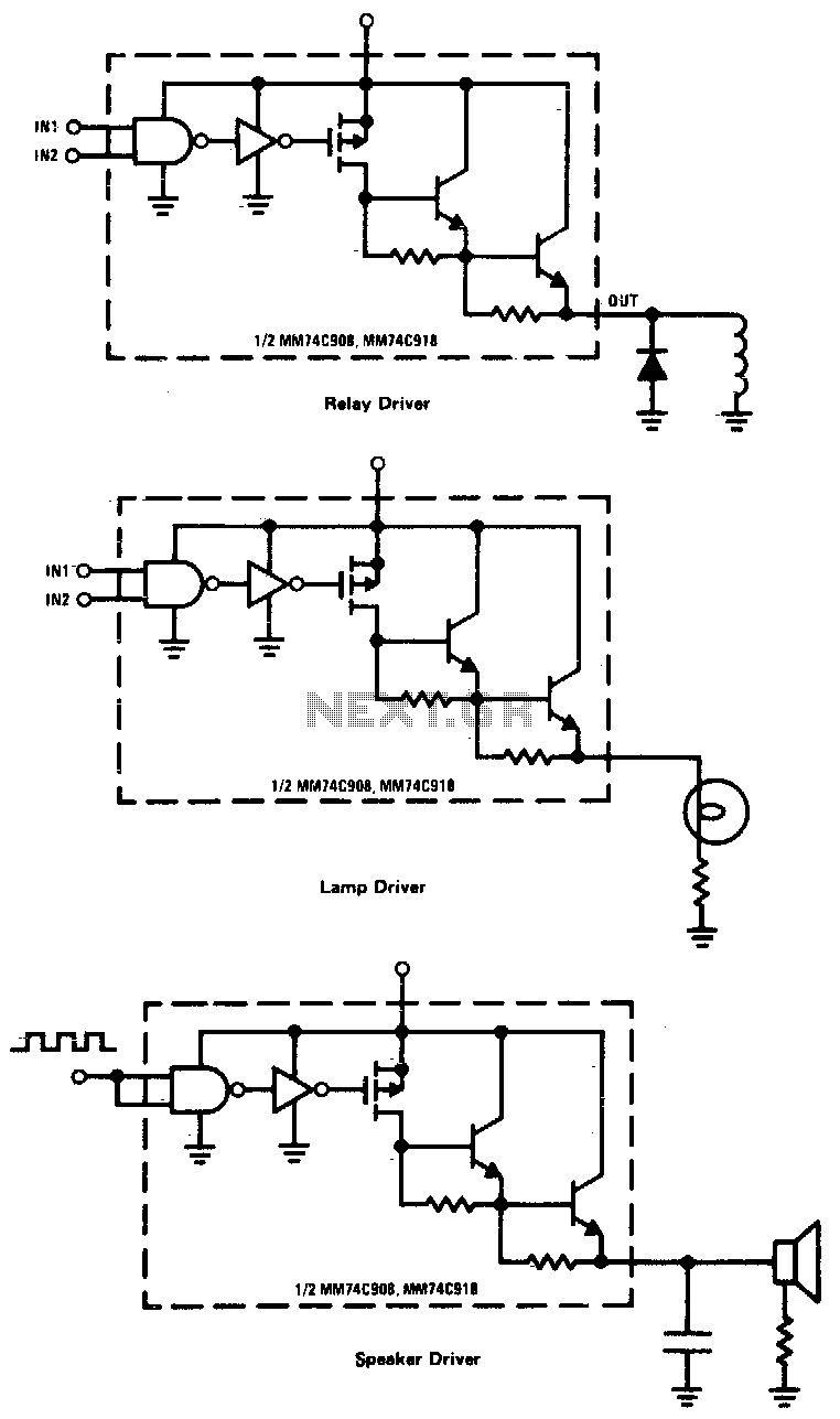
CMOS drivers for relays, lamps, speakers, and similar applications provide extremely low standby power consumption. When operating at Vcc = 15 V, the power dissipation per package is typically 750 nW when the outputs are not drawing current. Consequently,...
Adding a discharge path to the upper MOSFET of a cascode circuit significantly reduces the unavoidable Miller effect, thereby enhancing the Power Factor Correction (PFC) performance of a power supply's front end. In a cascode configuration, the upper MOSFET is...
The circuit depicted in Figure 3-121 illustrates the key component of an electromagnetic holding brake, which consists of an electromagnetic brake solenoid primarily made up of two parts: the iron core and the shoe brake components. When power is...
A 2 x 18W Hi-Fi Stereo Power Amplifier is designed using two TDA2030 integrated circuits (ICs). This amplifier features good input sensitivity, low distortion, stable operation, and comprehensive protection against overloads and output short-circuits. It can serve as a...
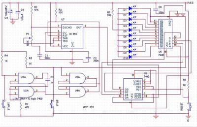
The speed test circuit is a simple design intended to measure a person's reaction time in a game. The operation of this peripheral is straightforward, facilitated by several integrated circuits, including a counter, timer IC, and decoder. The timer...
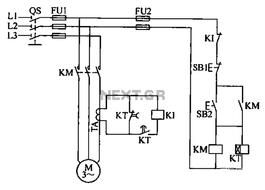
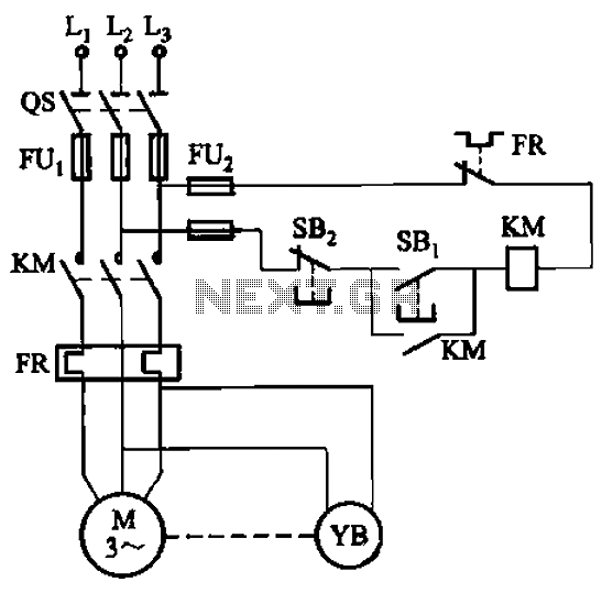
A three-phase electric motor overcurrent protection circuit. This example circuit utilizes a transformer to monitor the current, ensuring that the currents in the three-phase motor do not exceed normal operating levels. When the current exceeds the set threshold, the...