
Before power is in the hold state holding brake one circuit

The electromagnetic holding brake circuit operates through a solenoid mechanism that integrates seamlessly with the motor control system. The solenoid, designated as YB, serves as the primary actuator that controls the engagement and disengagement of the brake system. When the motor receives power, the solenoid coil is energized, creating a magnetic field that pulls the armature connected to the brake lever. This action lifts the brake lever, thereby retracting the brake shoes away from the wheel, allowing the motor to run freely.
The system is designed to ensure safety and efficiency. The brake shoes are held in a disengaged position during normal operation, but upon de-energizing the solenoid—typically initiated by the pressing of the stop button (SB2)—the magnetic field collapses. This results in the immediate release of the solenoid's hold on the brake lever, allowing the brake shoes to be forced back into contact with the wheel by a spring mechanism. This rapid engagement of the brake shoes effectively stops the motor, preventing any unintended motion and ensuring a controlled halt.
To enhance the reliability of the system, components such as the solenoid must be rated for the specific voltage and current requirements of the motor. The use of a robust spring mechanism is also critical, as it must be capable of providing sufficient force to engage the brake shoes quickly and effectively. Additionally, the circuit may include safety features such as fuses or circuit breakers to protect against overload conditions, ensuring the longevity of the components involved in the electromagnetic brake system.
In summary, the electromagnetic holding brake circuit is a vital component in motor control applications, providing a reliable means of stopping and holding the motor in place when necessary. The design and implementation of this circuit require careful consideration of the electrical and mechanical components to ensure optimal performance and safety. Circuit shown in Figure 3-121. The key component of electromagnetic holding brake is an electromagnetic brake brakes, brake solenoid which is mainly composed of two parts iron and shoe brake components. When the motor access to power, electromagnetic brake coil YB also was electric pull, forcing the brake lever is moved upward, from leaving the wheel brake and release the brake shoes on the brake, the motor running. When the motor power supply is cut off (press the stop button SB2) when, YB also missing, and released under the action of the brake shoes so that the spring force of the rapid wheel brake, the motor quickly stopped.
Related Circuits
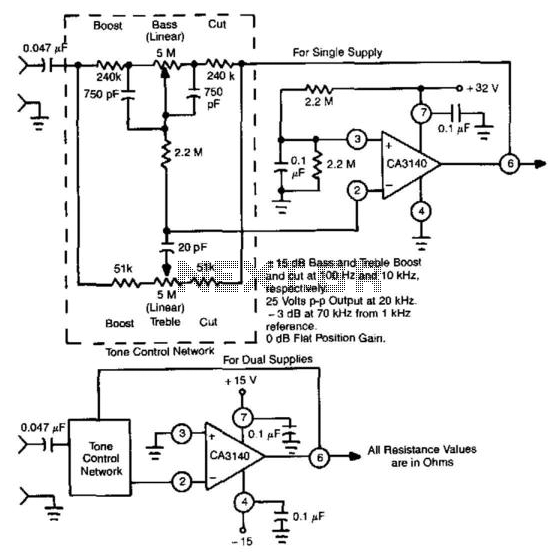
This circuit utilizes the high slew rate, high input impedance, and high output-voltage capability of the CA3140 BiMOS operational amplifier. It also offers mid-band unity gain using standard linear potentiometers. The circuit design leverages the characteristics of the CA3140 BiMOS...
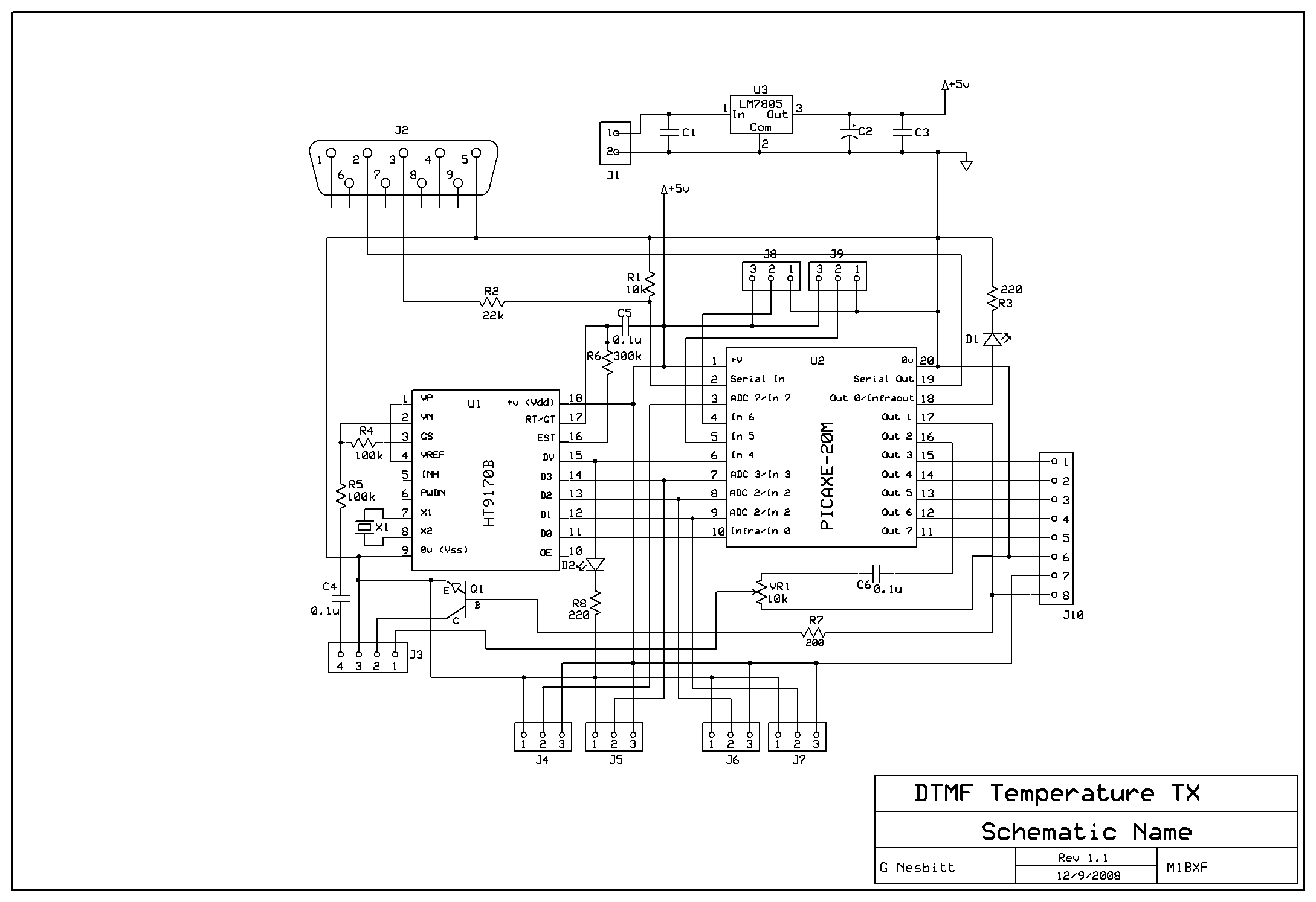
Remotely check the temperature of various items, specifically the repeater site at GB3PY. This system utilizes a radio to receive requests for the current temperature and sends the results back to the user. Requests are made using DTMF tones,...
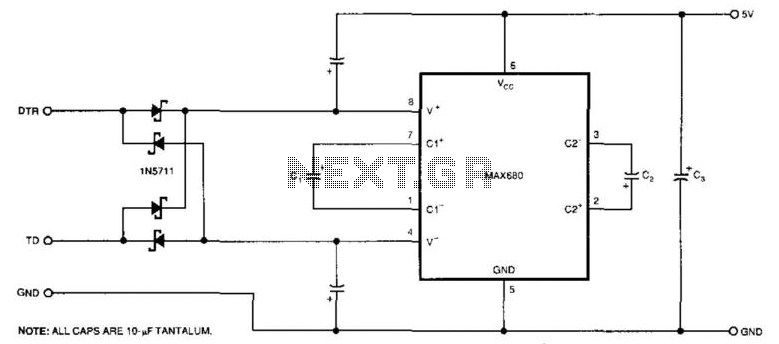
The circuit demonstrates a method for powering CMOS integrated circuits (ICs) using RS-232C lines. The MAX680 is typically employed to generate a voltage equal to ±2 Vcc. This circuit operates in the opposite manner, accepting ±10.5 to ±12V from...
The circuit consists of an ultrasonic transmitter and a receiver that operate at the same frequency. Ultrasonic piezoelectric transducers serve as the output and input devices, respectively, with their frequency of operation determined by the specific devices used. The...
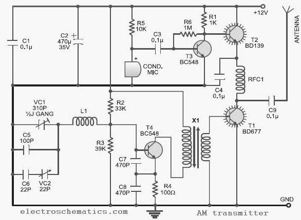
This low-cost AM transmitter is tunable from 10 to 15 MHz with the assistance of a ½J gang condenser VC1, which sets the carrier frequency of the amplitude modulation transmitter in conjunction with inductor L1. Frequency trimming can be...
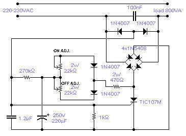
The circuit shown will switch on and off a resistive or inductive load up to 800VA with the possibility to adjust both the on and off period. Switching takes place during the zero crossing of the sine wave. The...