
Automatic lighting control circuit diagram composed of optocouplers

The described circuit operates as an automatic lighting control system that integrates both a delay mechanism and ambient light detection. The primary components include a triac, resistors, capacitors, and a reed switch, all of which work in conjunction to provide a seamless user experience. The triac (VT) serves as a crucial element for controlling the power to the hall lights, enabling them to turn on and off based on the door's status.
The operation begins with the door being closed, which keeps the reed switch (KD) in its normally closed state. When the door is opened at night, the removal of the magnet triggers the closure of the reed switch, allowing the capacitor (C1) to charge rapidly. The charging process is facilitated by the rectification of the 9V power supply through resistor R1, ensuring that the voltage across C1 rises swiftly, thus activating the light-emitting diodes and the thyristor to illuminate the hall lights.
The delay mechanism is an essential feature of this circuit. Once the door is closed again, the reed switch opens, interrupting the charging of C1. The capacitor then begins to discharge through resistor R3, gradually reducing the voltage. This discharge process is critical for determining the time duration that the lights remain on after the door is closed. The circuit is designed to ensure that the voltage across C1 falls below the threshold required to keep switches S1, S2, and S3 in the on state, thus turning off the lights after a set delay.
This automatic lighting control circuit is particularly useful for enhancing convenience and safety in residential settings, providing illumination when needed and conserving energy when it is not. Circuit is shown. Group 4 analog electronic circuit switch (S1 ~ S4): S1, S2, S3 for parallel delay circuit, when the power is turned on by their R4, VB6 drive Triac VT, VT dir ectly control the hall lights H; S4 and external photosensitive resistance RL and the like ambient light detection circuit. When the door is closed, mounted on the door frame normally closed reed KD action by the magnet on the door, its contacts open, S1, S2, S3 in the open state.
Night home owner opened the door, the magnet away from the KD, KD contact closure. After this time 9V power rectifier through R1 to charge C1, C1 two Swiss voltage quickly rises to 9V, the rectified voltage by S1, S2, S3 and R4 within the B6-emitting light-emitting diodes, triggering a two-way thyristor, H is lit., automatic lighting control. After the door closed, the magnet control KD, contact disconnect, 9V power to stop charging C1, entry delay circuit state, C1 began to discharge R3, after a time delay, C1 two Swiss voltage is gradually decreased to S1, S2, 83 open voltage (1.5v) or less, S1, S2, S3 resume off state, resulting in off VB6, VT also cut, H off, lights time-lapse function.
Related Circuits
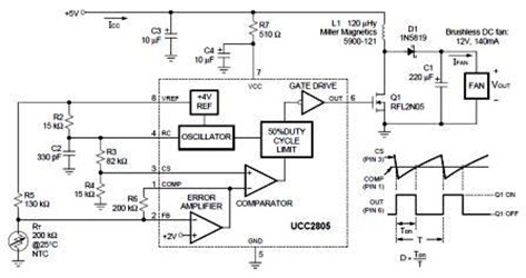
A temperature-controlled pulse-width-modulator (PWM) boost converter circuit diagram is illustrated in the following figure. This boost converter is designed to operate a 12V fan using a 5V supply while maintaining temperature control. The temperature-controlled PWM boost converter circuit operates by...
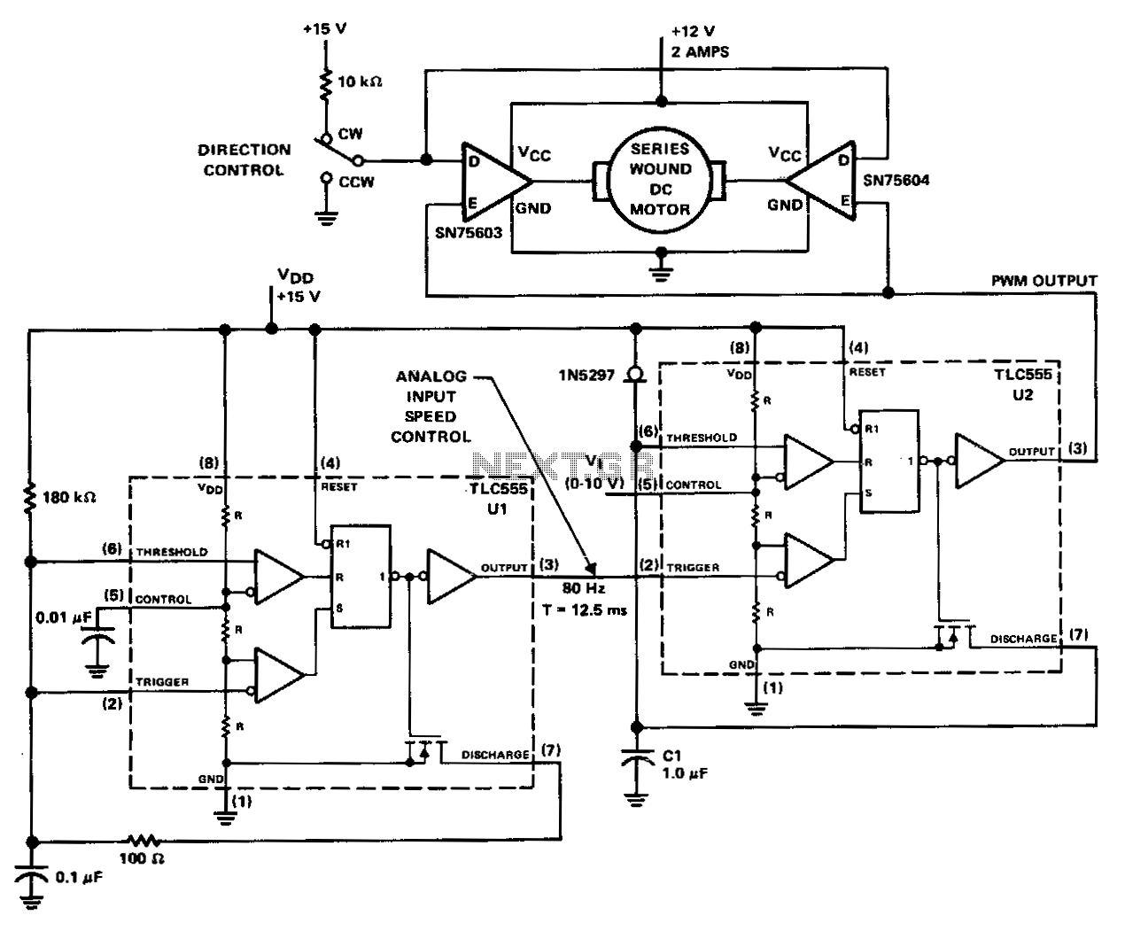
The PWM controller utilizes complementary half-H peripheral drivers SN75603 and SN75604, featuring totem-pole outputs rated at 40 V and 2.0 A. These drivers effectively configure the motor in a full-bridge setup, enabling bidirectional control. Timer U1 operates in astable...

I have been sourcing my MOSFETs from Allied, as they are significantly more affordable than those from Digi-Key. The choice of MOSFETs (Metal-Oxide-Semiconductor Field-Effect Transistors) is crucial in electronic circuit design, particularly in applications requiring efficient switching and amplification. When...
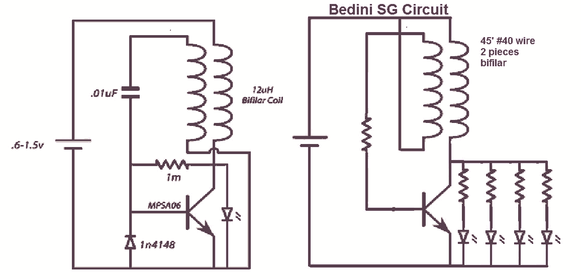
It would be beneficial to obtain schematics of the Joule Thief and Bedini oscillator circuit connections. This is an area that has not been previously explored. The schematic on the left was sourced from the Energetic Forum, while the...
This system is designed to communicate or transmit a text message from one location to another using a wireless circuit. The text message is encrypted with a microcontroller, and the encrypted message is transmitted wirelessly. At the receiving end,...
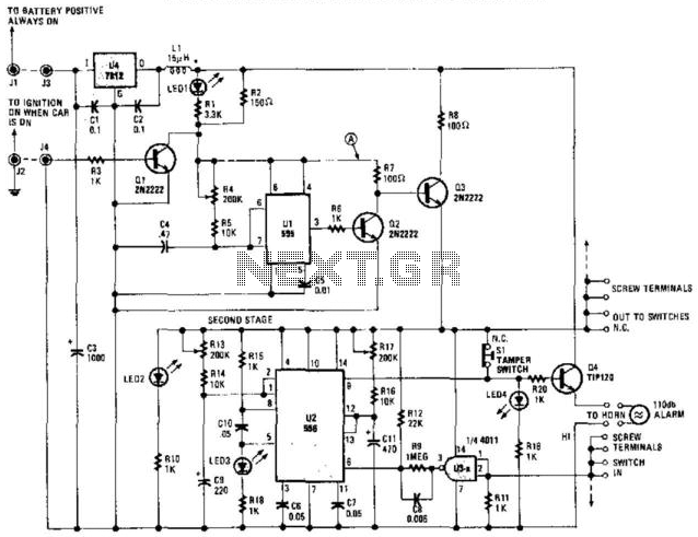
The circuit automatically activates when the car is turned off, providing a variable time for the user to exit and secure the vehicle. It also offers a variable time delay for entering and starting the car. The 555 oscillator/timers...