
joule thief Bedini oscillator circuit

The Joule Thief is a simple circuit designed to extract energy from a low-voltage source, typically a single AA battery, and boost it to a higher voltage suitable for powering small devices, such as LEDs. This circuit typically consists of a few key components: a transistor, a transformer (often a toroidal ferrite core with a bifilar winding), a resistor, and a capacitor. The operation of the Joule Thief relies on the principles of electromagnetic induction and feedback. When the circuit is powered, the transistor turns on, allowing current to flow through the primary winding of the transformer, which magnetically induces a current in the secondary winding. When the transistor turns off, the collapsing magnetic field induces a high voltage spike in the opposite direction, which can be used to power the load.
The Bedini oscillator, on the other hand, is a more complex circuit that serves as a pulse motor and energy recovery system. It typically includes a transistor, a flyback transformer, and several capacitors and resistors. The Bedini oscillator operates by creating a pulsing magnetic field that can drive a rotor or generate electrical energy. The circuit is designed to capture and recycle energy that would otherwise be wasted, making it a popular choice among enthusiasts interested in overunity devices or free energy concepts. The Bedini circuit can be configured in various ways, depending on the desired application, and can include additional components such as diodes for rectification and capacitors for energy storage.
Both circuits exemplify innovative approaches to energy utilization and showcase the principles of electromagnetic theory in practical applications. Understanding their schematics and operation can provide valuable insights into low-power energy harvesting and conversion techniques.It would be really nice to get schematics of the joule thief and Bedini oscillator circuit connections. Thats something I havent tried. The one on the left, I found here on the energetic forum. The one on the right I copied from a 2011 video from a Bedini presentation video. 🔗 External reference
Related Circuits

This design circuit is intended for sine wave oscillators, providing both sine and square wave outputs across a frequency range from below 20 Hz to above 20 KHz. The oscillation frequency can be easily adjusted by changing a single...
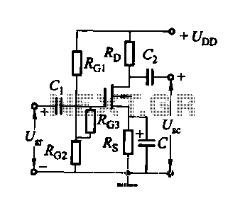
FET several basic bias circuit - self-bias voltage divider circuit The self-bias voltage divider circuit is a fundamental configuration used in Field Effect Transistor (FET) biasing. This circuit employs two resistors to create a stable bias voltage for the transistor's...
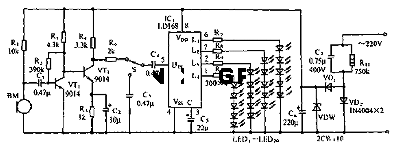
The circuit depicted in the figure involves the LD168, which functions as a sound level indicator for tape recorder speakers. It features four outputs capable of directly driving multiple light-emitting diodes. Additionally, the device can be activated by a...

A basic LED driver circuit consists of a 5-volt power source, a 2 kΩ potentiometer, and an LED. The LED is forward biased, with the manufacturer specifying a maximum current rating of 20 mA at a diode voltage drop...
This is a INA159 Dual-Polarity, Bidirectional Current-Shunt-Monitor Circuit. This circuit uses OPA340 because it has near rail-to-rail input and output swing. The INA159 is an integrated circuit designed for high precision current sensing applications. It is capable of measuring bidirectional...
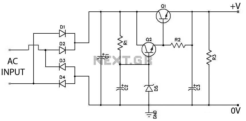
Low Ripple Regulated Power Supply Circuit Diagram. This circuit can be employed in applications requiring high current with minimal ripple voltage, such as in high-powered class AB amplifiers where high-quality audio reproduction is essential. The low ripple regulated power...