
automatic low power emergancy light

The emergency light circuit operates efficiently by integrating multiple components to ensure reliable performance during power outages. The LM317 regulator serves as the backbone of the charging circuit, allowing for voltage adjustments that cater to different battery specifications. The use of a transformer to step down the AC voltage is critical, as it ensures that the subsequent components receive the correct voltage levels for optimal operation.
The bridge rectifier converts the AC voltage into DC, which is essential for charging the battery and powering the LEDs. The inclusion of a filter capacitor (C1) is crucial in smoothing out any voltage fluctuations, thereby protecting sensitive components from potential damage. The current limiting resistor (R15) and diode (D5) work in tandem to regulate the charging current, preventing overcharging and extending the battery's lifespan.
The functionality of the system is further enhanced by the transistor Q2, which acts as a switch to control the LED illumination based on mains availability. This automatic switching mechanism is vital for emergency lighting, ensuring that the LEDs only activate when needed. The circuit's design allows for scalability, accommodating additional LEDs as long as the total current remains within safe limits. Proper thermal management for Q2 is also a key consideration, as excessive heat can lead to component failure.
Overall, this emergency light circuit is a robust solution for providing illumination during power outages, with features that ensure safety, reliability, and ease of use. The careful selection of components and thoughtful design considerations contribute to a highly functional and efficient lighting solution.A white-LED-based emergency light that offers the following advantages. 1-It is highly bright due to the use of white LEDs. 2-The light turns on automatically when mains supply fails, and turns off when mains power resumes. 3-It has its own battery charger. When the battery is fully charged, charging stops automatically. The charger power supply section is built around 3-terminal adjustable regulator IC LM317 (IC1), while the LED driver section is built around transistor BD140 (Q2). In the charger power supply section, an input AC main is stepped down by T1 to deliver 9V, 500mA to the bridge rectifier, which comprises diodes D1 through D4.
Filter capacitor C1 eliminates ripples. Unregulated DC voltage is fed to input pin 3 of IC1 and provides charging current through D5 and limiting resistor R15. By adjusting preset P1, the output voltage can be adjusted to deliver the required charging current. When the battery gets charged to 6. 8V, D6 conducts and charging current from IC1 finds a path throughQT1 to ground and it stops charging of the battery.
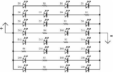
When mains power is available, the base of Q2 remains high and Q2 does not conduct. Thus LEDs are off. On the other hand, when mains fails, the base of Q2 becomes low and it conducts. This makes all the LEDs glow. The mains power supply, when available, charges the battery and keeps the LEDs off as Q2 remains cut-off. During mains failure, the charging section stops working and the B1 supply makes the LEDs glow. Assemble the circuit on a general-purpose PCB and enclose in a cabinet with enough space for battery and switches.
We have tested the circuit with twelve 10mm white LEDs. You can use more LEDs provided the total current consumption does not exceed 1. 5A. Driver transistor Q2 can deliver up to 1. 5A with proper heat-sink arrangement. 🔗 External reference
Related Circuits
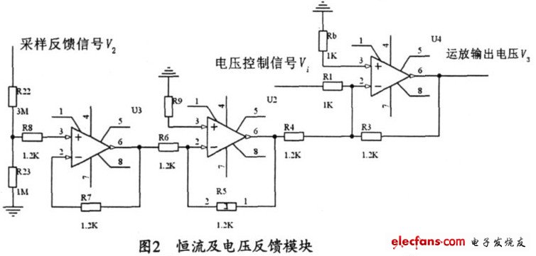
The output current range of the parameter current regulator is limited, and its precision is not high. Connecting the feedback adjustment type output current of the current-stabilized power source in series results in lower efficiency. The steady current source...
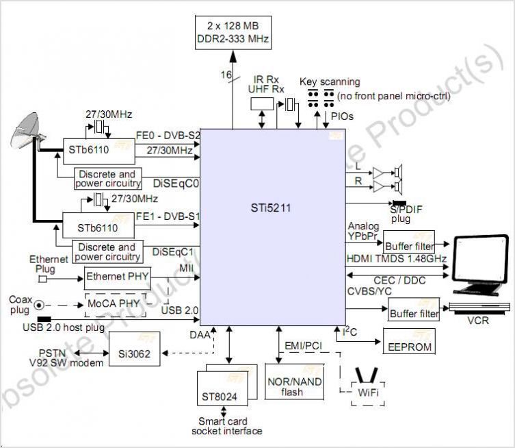
The STI7167 utilizes advanced process technology to deliver a fully featured HD AVC DVB-C and DVB-T demodulator and decoder integrated circuit (IC). This highly integrated system-on-chip is designed for set-top box (STB) markets across cable, terrestrial, and terrestrial/IP hybrid...
A light-emitting diode (LED) lamp is a solid-state lighting device that utilizes light-emitting diodes as its light source. LEDs are a cost-effective and convenient choice for various lighting applications. They are available in an extensive range of colors, styles,...
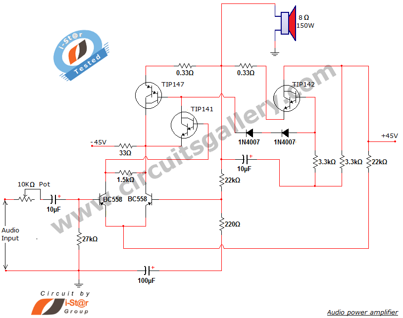
This document presents a new audio power amplifier schematic utilizing TIP darlington pair transistors. It is suitable for both home audio and car audio amplifiers. The TIP142 and TIP147 darlington pair transistors create a push-pull high-power amplifier configuration, while...
A hybrid amplifier is being developed, utilizing an Aikido configuration for the voltage amplification stage (VAS) and an emitter-follower variation for the output stage (OPS). The hybrid amplifier design integrates two distinct amplification stages to achieve high performance and...
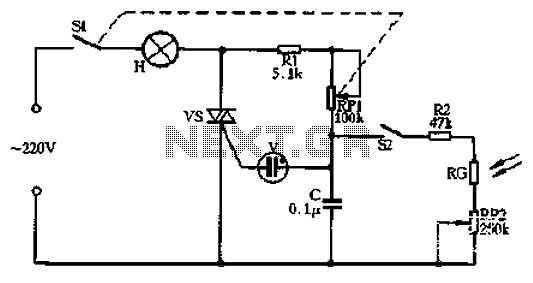
Circle S2 is a stable automatic light switch. When S2 is open, the entire circuit operates as a subsection II SCR stepless presentation dimmer, omitting the high-frequency filter circuit. The trigger diode switch activates a neon indicator bulb (V),...