
Simple home audio power amplifier circuit schematic

This audio power amplifier circuit is designed for high efficiency and low distortion, making it suitable for a variety of audio applications. The TIP142 and TIP147 transistors are selected for their high current gain and ability to handle significant power levels, which are essential for driving larger speakers effectively. The push-pull configuration allows for better performance in terms of linearity and reduced crossover distortion, which is particularly important in audio amplification.
The preamplifier stage, formed by the BC558 transistors, plays a crucial role in amplifying the weak audio signal before it reaches the power amplifier stage. This differential amplifier configuration enhances the signal-to-noise ratio, ensuring that the audio output remains clear and free from unwanted noise. The 10 µF DC decoupling capacitor is vital in blocking any DC offset present in the audio signal, which could otherwise affect the performance of the amplifier.
The power supply requirements of +/-40V at 5A ensure that the amplifier can deliver its full rated power without distortion. The specified 30V-0-30V transformer is suitable for providing the necessary voltage levels for the dual power supply, allowing the amplifier to operate efficiently under various load conditions.
Overall, this audio power amplifier schematic represents a cost-effective and efficient solution for audio amplification needs, making it an excellent choice for hobbyists and professionals alike. The detailed component specifications and circuit design ensure that users can replicate the circuit with ease, achieving high-quality audio performance in their applications.Here is a new audio power amplifier schematic built around TIP darlington pair transistors. You can use this circuit for home audio power amplifiers and car audio amplifiers. The TIP142 and TIP147 darlington pair transistors forms a push pull high power amplifier configuration while the two BC558 PNP transistor provides a mini audio pre amplifier circuit. The audio signal is applied to the pre amp through a capacitor, then it is coupled to the push pull power amp via TIP141 transistor. The values and ratings of different components of power amplifier design are also given in this article.
Implementation cost of this mini audio amplifier circuit is too cheap, near $5. The circuit can deliver 150 W RMS to a 8 © (150 Watt power amplifier). Our new audio power amplifier project is based on TIP 142 and TIP 147 (complementary darlington pair power transistors which can handle 5 A current and 100V). The two PNP (BC 558) transistors forms a pre amplifier section to the preceding high power push pull amplifier built around TIP141, TIP 142 and TIP 147 darlington pair transistors.
We are using 2 PNP transistors to form a preamplifier section, it is nothing but a differential amplifier to improve overall performance of the amplifier. The application of a differential amplifier in the input phase reduces noise. Input signal is applied to the differential amplifier section via 10 µF DC decoupling capacitor. Capacitor removes the DC voltage from the input audio signal. A complementary class AB push pull power amplifier stage is built around the TIP darlington pair transistors to drive the 8 © 150 watt speaker (The circuit can deliver 150 W RMS to a 8 ©).
+/-40V, 5A dual power supply is necessary to provide supply for this simplest amplifier circuit. Use 30V-0-30V step down transformer and construct a dual lab power supply for this project. 🔗 External reference
Related Circuits
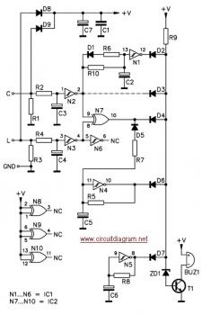
The circuit is designed to ensure that the headlights or side lights are automatically switched off after the ignition contact is turned off. This prevents the occurrence of a dead battery due to headlights being inadvertently left on. The circuit...
This light alarm schematic circuit is designed using common electronic components, as illustrated in the circuit diagram below. The light alarm circuit will activate an alarm as soon as the drawer is opened and light falls on the Darlington...
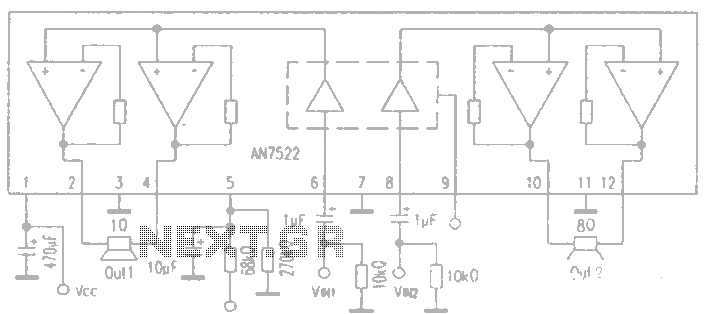
AN7522 is a Panasonic stereo audio amplifier IC that delivers an output power of 3W at 8 ohms. It features a standby function, low static power consumption, and reduced noise levels, requiring fewer external components for stable operation. This...
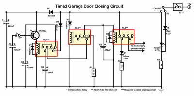
Timer garage door circuit schematic diagram, printed circuit board. The timer garage door circuit is designed to automate the opening and closing of a garage door based on a predetermined time interval. The schematic diagram illustrates the layout and connections...
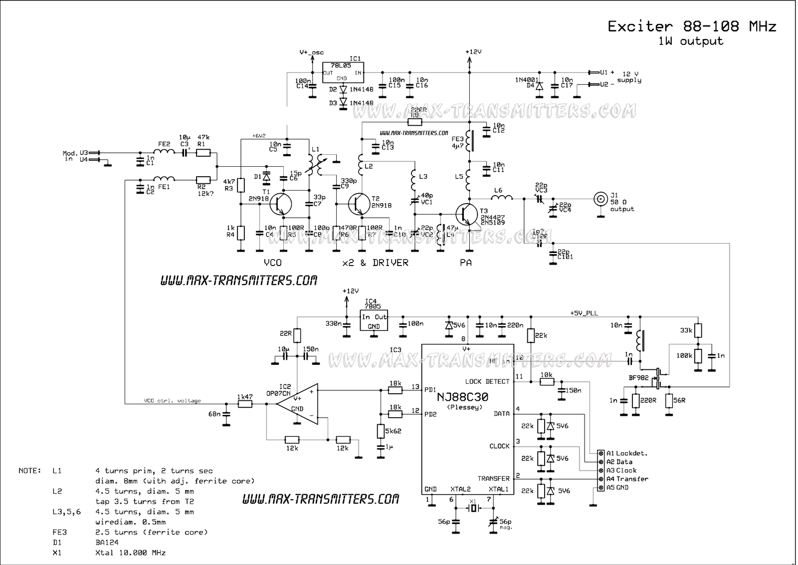
A compact FM transmitter designed for educational purposes. The RF section of this transmitter can be easily integrated into various projects. However, utilizing the PLL feature requires knowledge of constructing a serial data link and connecting the LPFM transmitter...
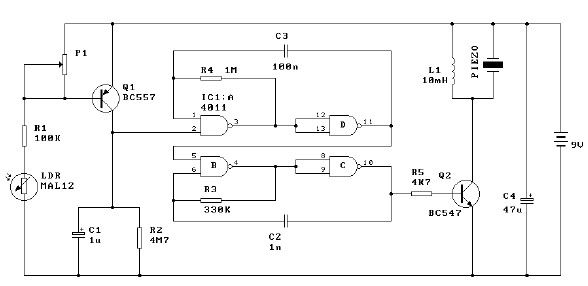
Two-Tone Siren Circuit Schematic Using One IC. This circuit is designed for children's entertainment and can be installed on bicycles, battery-powered cars, motorcycles, as well as models and various games and toys. It includes a switch (SW1) for operation. The...