
Automatic range switching circuit diagram PGA202

The automatic range switching circuit is designed to optimize the gain of the programmable gain amplifier (PGA202) based on the output voltage (VOUT) in relation to a reference voltage (VREF). This circuit employs voltage comparators to monitor VOUT continuously. When VOUT surpasses the threshold of 10V, the comparator's output transitions to a low state, signaling the up/down counter to decrement the gain of the PGA202. This decrement is implemented through a 2-bit binary code sent to the A0 and A1 pins of the PGA202, effectively reducing the amplifier's gain to prevent saturation and maintain signal integrity.
In contrast, when VOUT drops to approximately 0.909V, which is derived from the voltage divider formula [1k/(1k + 10k)] * 10V, the comparator's output switches to a high state. This change instructs the up/down counter to increment the gain of the PGA202, again using a 2-bit binary code directed to the A0 and A1 pins. The ability to dynamically adjust the gain based on VOUT ensures that the circuit can accommodate a wide range of input signal amplitudes, thus enhancing the performance and adaptability of the system in various applications.
The design of this circuit necessitates careful consideration of component specifications, such as the response time of the comparators and the resolution of the up/down counter, to ensure that the switching occurs promptly and accurately. Additionally, the choice of resistors in the voltage divider impacts the threshold levels and, consequently, the overall performance of the automatic range switching mechanism. This circuit is particularly useful in applications where signal amplitudes may vary significantly, requiring robust gain control to maintain optimal performance. As shown in FIG grounds PGA202 and comparators, counters constitute automatic range switching circuit. The circuit at the output of the comparator compares VOUT when VOUT VREF 10V, the comparator outputs down signal, up/down counter output 2Bit coding PGA202 of A0, A1 side to make the PGA202 gain decrease; when VOUT [1k/(1k + 10k )] 10V 0.909V, the comparator outputs l signal, up/down counter output 2Bit coding to A0, A1 end PGA202 and PGA202 make the gain increases.
Related Circuits
This circuit generates the power required to operate a bipolar stepper motor. It allows for adjustments in both the rotation speed and direction of the motor. The design includes two integrator circuits (A1, A3) and an amplifier (A2) connected...
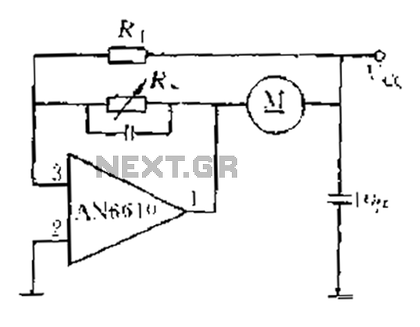
AN6610 Application Circuit operates as follows: When the supply voltage (Vcc) changes due to mechanical load variations, it can affect the motor speed. The motor speed is proportional to the back electromotive force (EMF). Consequently, the voltage across the...
In many instances, the dimmer described here may be integrated into a wall-mounted box that also contains the light switch. It is designed specifically for use with 240 V incandescent lamps. Upon activation, the lamp does not reach full...
Figure 14-41 illustrates a multivibrator circuit utilizing a 555 timer alongside various capacitive and resistive components. The oscillation frequency is determined by the values of Ra, R16, and C3, following the formula f = 1.44 / ((Ra + 2R16)...
There are two differing opinions regarding the charging of alkaline batteries. Some assert that charging is effective, while others caution against it due to the risk of explosion. It is acknowledged that rechargeable alkaline batteries can typically endure 30...
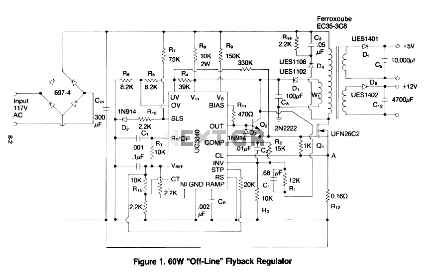
This paper gives a practical example of the design of an off-line switching power supply. Factors governing the choice of a discontinuous flyback topology are discussed. The design uses a pulsed-width modulation (PWM) control scheme implemented with a Unitrode...