
555 simple electronic keyboard circuit (2)
")
The multivibrator circuit based on the 555 timer is a versatile configuration used for generating pulse-width modulation signals, oscillations, and timing applications. The core of the circuit relies on the 555 timer IC, which can operate in astable, monostable, or bistable modes. In this configuration, it operates in astable mode, where it continuously oscillates between high and low states, generating a square wave output.
The frequency of oscillation, as indicated, is calculated using the formula f = 1.44 / ((Ra + 2R16) * C3). Here, Ra is the resistance value that can be adjusted by selecting different resistors from R1 to R15, allowing for flexibility in the circuit's frequency response. R16 serves as an additional resistor that influences the timing characteristics, while C3 is the timing capacitor that works in conjunction with the resistors to set the frequency of oscillation.
The keys K1 to K15 can serve as input controls that modify the resistance value of Ra. When a key is pressed, it can either connect or disconnect certain resistors in parallel or series, thus changing the effective resistance and, consequently, the frequency of the output signal. This feature allows for user interaction, enabling dynamic adjustments to the oscillation frequency based on operational requirements.
During the debugging phase, it is crucial to monitor the output waveform using an oscilloscope to ensure that the desired frequency and duty cycle are achieved. Adjustments can be made to the resistor and capacitor values to fine-tune the performance of the multivibrator. Additionally, it is advisable to take note of any anomalies in the output that could indicate issues with component values or connections within the circuit. Proper documentation of these observations will facilitate troubleshooting and optimization of the multivibrator circuit.As the figure 14-41 shows, the multivibrator is composed of the 555 and some capacitance resistance components, the oscillation frequency depends on the values of Ra, R16 and C3. f=1.44/(Ra+2R16)C3, the Ra of the formula corresponds to the different values of R1-R15, this depends on the situation of the keys K1-K15.
When you are debugging the notes, you can.. 🔗 External reference
Related Circuits

This battery saver circuit can automatically turn off a small piece of test equipment after a desired period of time, allowing for worry-free operation in a workshop environment. The circuit utilizes a CD4011 integrated circuit (IC) to function as...
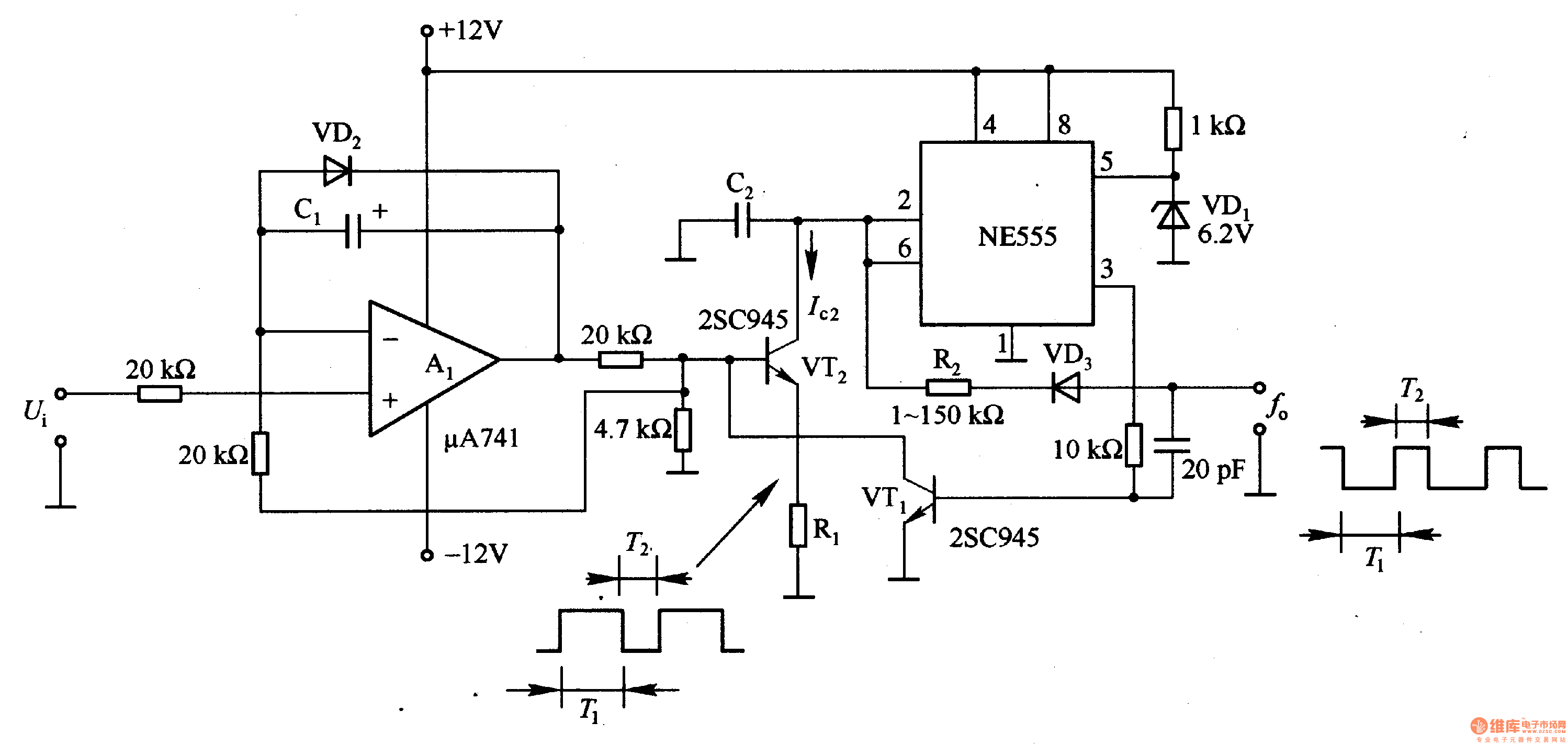
In the circuit, the oscillation frequency of the NE555 is controlled by VT2. When the output at pin 3 is low (during the T1 period), VT1 stops conducting, and VT2 begins to conduct with a current Ic2 flowing through...
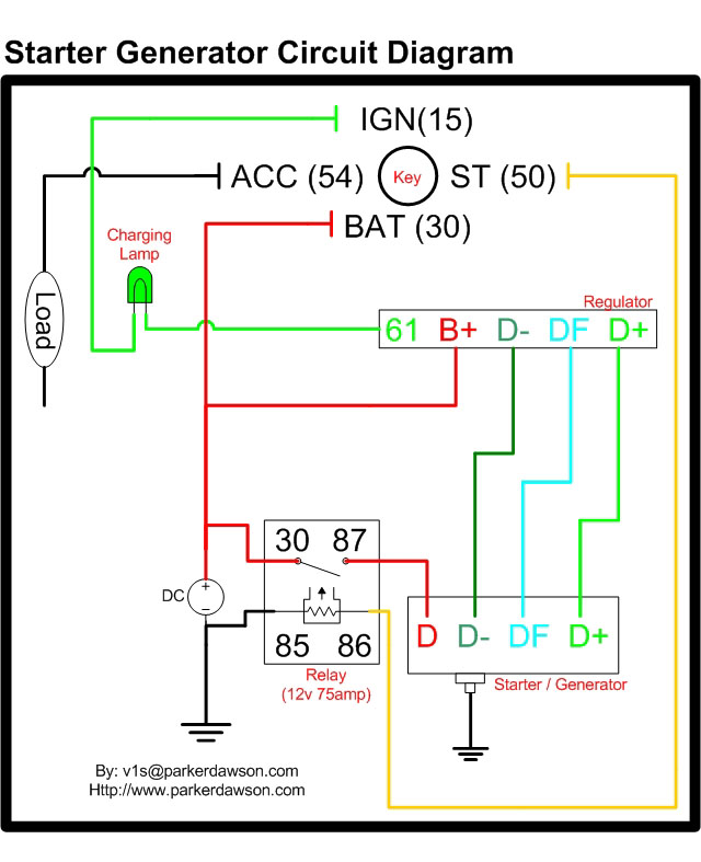
Circuit diagrams for both a Bosch and a Delco-Remy Starter-Generator are available, noting that the circuits differ. Due to a computer crash, the original diagrams and the associated email address were lost. However, in May 2004, both the email...

To prevent deep discharge that can damage or shorten the life of a rechargeable battery, it is essential to disconnect its load before the battery is completely discharged. The circuit protects against AC line disturbances by switching off the...
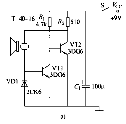
The ultrasonic transmitter circuit T-40-16, along with various discrete components, functions as a feedback sensor. The transistors VT1 and VT2 create a robust positive feedback oscillator that converts an electric signal into an ultrasonic oscillation signal, with the oscillation...
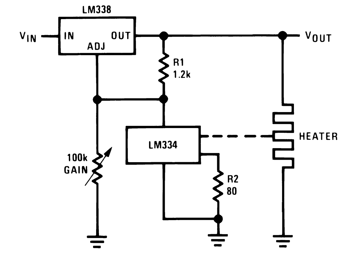
This power supply utilizes a single 7812 IC voltage regulator along with multiple external pass transistors, enabling it to deliver output load currents of up to 30 amps. The circuit design incorporates a 7812 linear voltage regulator, which is...