
Automatic Room Lights With NE555 IC

The automatic room light circuit is designed to enhance energy efficiency and convenience by utilizing a memory component, typically a flip-flop or a microcontroller, to control the lighting based on occupancy or ambient light levels. The circuit generally consists of several key components: a light sensor, a relay, a memory element, and a power supply.
The light sensor, often a photoresistor or phototransistor, detects the ambient light level in the room. When the light level drops below a certain threshold, indicating that it is dark, the sensor sends a signal to the memory component. The memory component retains the state of the circuit, ensuring that the light remains on until the sensor detects sufficient ambient light, at which point it sends a signal to switch off the light.
The relay acts as a switch that controls the power to the light fixture. When activated by the memory component, the relay closes the circuit, allowing current to flow to the light bulb, thus illuminating the room. Conversely, when the memory component receives a signal from the light sensor indicating that the ambient light level is adequate, the relay opens, cutting off the power to the light bulb.
The power supply provides the necessary voltage and current to operate the circuit components. It is crucial to ensure that the power supply is compatible with the specifications of the light bulb and the control circuitry.
This circuit can be further enhanced with additional features, such as adjustable sensitivity for the light sensor, a timer to limit the duration the light stays on, or integration with a motion sensor for increased automation. These enhancements can improve the responsiveness and functionality of the automatic room light circuit, making it suitable for various applications in residential and commercial settings.This circuit shows an automatic room light circuit diagram. It has a small memory which enables it to automatically switch `on` and switch `off` .. 🔗 External reference
Related Circuits
An emergency light system utilizing white LEDs, which provides several advantages: 1. It is highly bright due to the use of white LEDs. 2. The light activates automatically during a mains power failure and deactivates when mains power is...
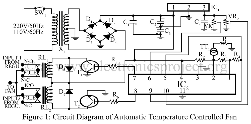
An automatic temperature-controlled fan regulates the fan speed based on temperature variations using the temperature transducer AD590 and an op-amp LM324 circuit diagram. The automatic temperature-controlled fan circuit utilizes the AD590 temperature transducer, which provides an output voltage that is...
The operational theory of this infrared automatic hand washing device circuit includes a power supply, an infrared transmitting circuit, an infrared receiving circuit, and a control circuit. The circuit is illustrated in figure 9-121. The power supply circuit consists...
This circuit allows the user to turn off a lamp using a switch located far from the bed, providing sufficient time to lie down before the lamp switches off. Due to its low current consumption, the circuit can be...
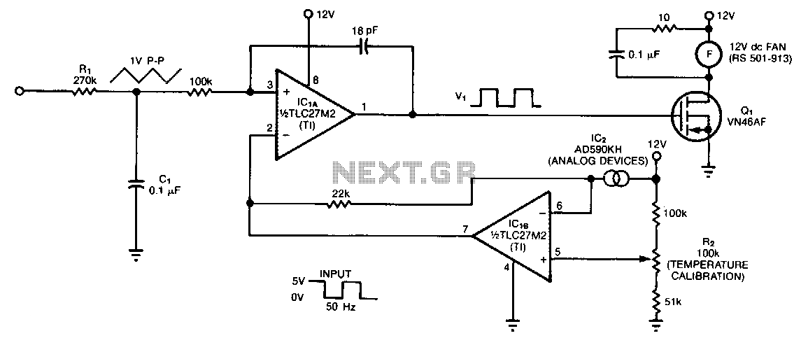
The controller circuit is designed to reduce a fan's noise, power consumption, and wear, especially when operating in low, fluctuating ambient temperatures. A temperature sensor is mounted in the fan's airstream, allowing the circuit to adjust the fan speed...
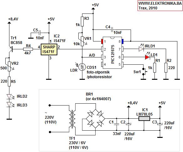
This device functions as a module for a Dual Channel IR Remote Control. It serves as a sophisticated switch with a timer for door operation, emphasizing modularity and wireless functionality. The device measures ambient light levels using a CdS...