
Automatic Room Power ControlCircuit CD4017 IC

The Automatic Room Power Control Circuit utilizes an NE555 timer IC configured in a monostable or astable mode, depending on the desired functionality. The primary purpose of this circuit is to automatically control the power supply to a room based on ambient light levels detected by the LDRs.
In this circuit, two LDRs are strategically placed to sense the light intensity from different angles or areas within the room. As the light intensity changes, the resistance of the LDRs varies, which in turn affects the voltage at the input of the NE555 timer. When the light level drops below a certain threshold, the NE555 activates an output that can control a relay or a transistor, thereby switching on the power to the room's lighting or other electrical devices.
The circuit may include additional components such as resistors and capacitors to set the timing intervals and to stabilize the voltage levels. The output stage typically consists of a relay that can handle higher current loads, allowing for the control of multiple devices without overloading the NE555.
This circuit is ideal for energy-saving applications, ensuring that lights are turned on only when necessary and automatically switching off when sufficient natural light is available, thereby conserving electricity and enhancing convenience in everyday usage.The following circuit shows about Automatic Room Power Control Circuit Diagram. This circuit based on the NE555 IC. Features: uses two LDRs, use .. 🔗 External reference
Related Circuits
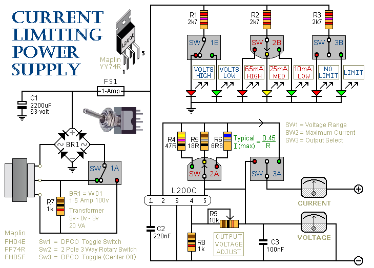
This is a 1-amp variable-voltage power supply unit (PSU) that can adjust the output voltage from approximately 3V to 24V. It includes a feature that allows for the limitation of the maximum output current, which is particularly useful when...
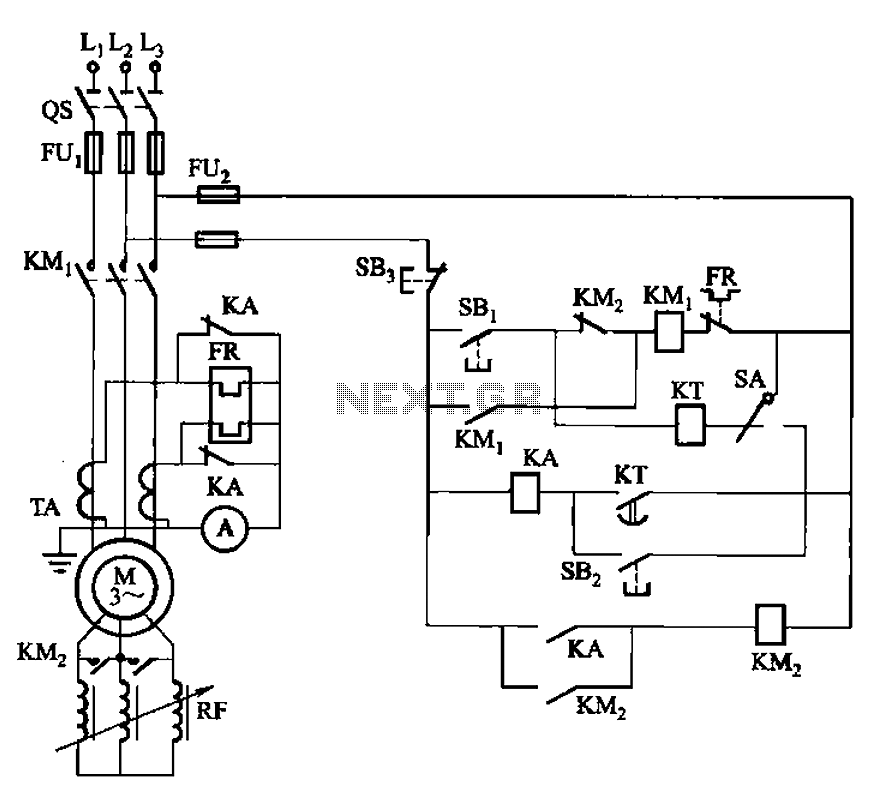
The circuit shown in Figure 3-164 can operate in both manual and automatic modes. During startup, the normally closed contact of relay KA is shorted, which affects the heating element to avoid prolonged startup times that could lead to...
The schematic of the power supply is illustrated below. It operates using standard household power of 120VAC at a frequency of 50/60Hz, with an adjustable output that can reach up to 25kV or higher. The power supply circuit is designed...
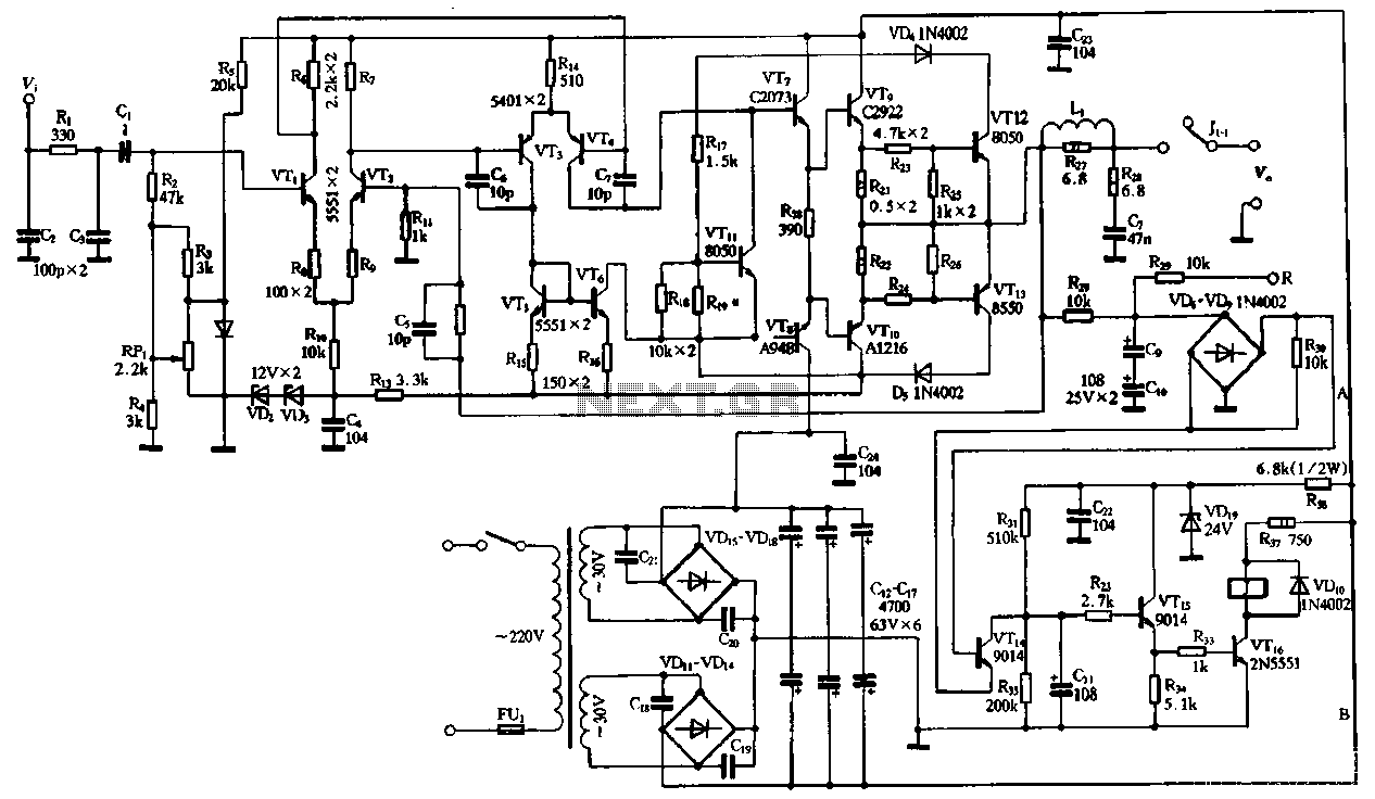
The performance of the amplifiers 2SC2922 and 2SA1216 (or 2SC3264 and 2SA1295) is excellent, featuring good linearity and strong overload capabilities. These devices are utilized as high-fidelity power amplifier stages, demonstrating outstanding performance. The circuit, as illustrated in Figure...
The circuit described below is notable for its low power consumption. With a 9V input and no load at the output, it draws only 50 mA, which is significantly lower than the quiescent current of a 78L05 regulator. The...
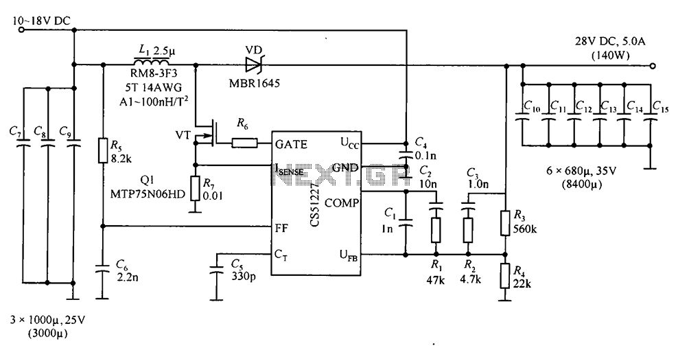
CS51227 is a voltage-type PWM controller that delivers an output of 28V with a maximum current of 5A. The switching frequency is 1.0 MHz, with a starting voltage of 4.7V and a starting current of 75A. The input voltage...