
Automatic street light circuit

The circuit utilizes a Light Dependent Resistor (LDR) as the primary sensor for detecting ambient light levels. The LDR is a variable resistor that changes its resistance based on the intensity of light it receives; it has low resistance in bright light and high resistance in darkness. This property is fundamental to the operation of the circuit.
When the ambient light level is high (daytime), the LDR’s low resistance keeps the base of the PNP transistor Q1 at a higher voltage than its emitter, thus keeping Q1 in the OFF state. As a result, Q2, which is connected to the emitter of Q1, also remains OFF, preventing current from flowing through the TRIAC, which means the lamp remains OFF.
As the sun sets and the light level decreases, the resistance of the LDR increases. This change allows the base-emitter junction of Q1 to become forward-biased, turning Q1 ON. Consequently, Q2 also turns ON, allowing current to flow through the TRIAC. The TRIAC then completes the circuit, enabling the lamp to turn ON.
The sensitivity of the circuit can be adjusted using R1, which is in series with the LDR. By changing the resistance of R1, the threshold light level at which the circuit switches from OFF to ON can be fine-tuned. Additionally, R2 can be adjusted to further refine the sensitivity and responsiveness of the circuit to changing light conditions.
This design is particularly useful for automatic lighting systems, such as garden lights or street lights, where the control of illumination based on natural light levels is desired. The combination of transistors and a TRIAC provides a robust mechanism for controlling higher power loads, such as incandescent or LED lamps, while ensuring that the circuit operates efficiently and reliably.Below shown circuit will be automatically switched ON and OFF during night and morning times respectively. In above circuit R1 can be used to adjust the sensitivity. And the working of the circuit is very simple. The LDR will have very low resistance during day time so the transistor Q1 will be in OFF condition. And during night time the resistance will be very high so automatically the transistor Q1 will be ON. The Q1 is PNP transistor and the emitter of Q1 is given to base of Q2. So the Q2 transistor will be ON only if the transistor Q1 is ON. The TRIAC is used in the circuit to make is circuit complete. As the TRIAC will allow voltage to pass from either directions only when there is a certain threshold voltage in gate terminal. And the gate of TRIAC is controlled by transistor Q2. So totally the lamp will be ON during night time and will be again switched off during day light. To change the sensitivity of the circuit to light adjust R2. 🔗 External reference
Related Circuits
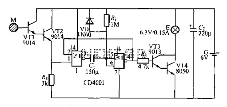
A two-battery powered light touch delay circuit designed for convenience at night. It can be placed on a bed pillow, and when the metal contact M under the capsule is touched, a small lamp will automatically light up. The...
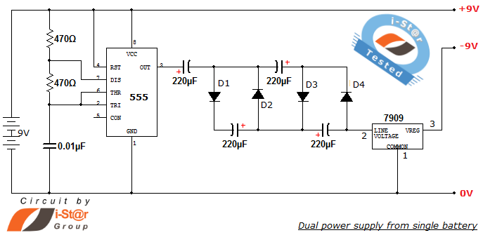
How to create a dual power supply unit using a single battery for laboratory purposes. Dual voltage power supplies are particularly needed for operational amplifier experiments and some instrumentation amplifiers. Additionally, certain low-power audio preamplifiers also require dual voltage...
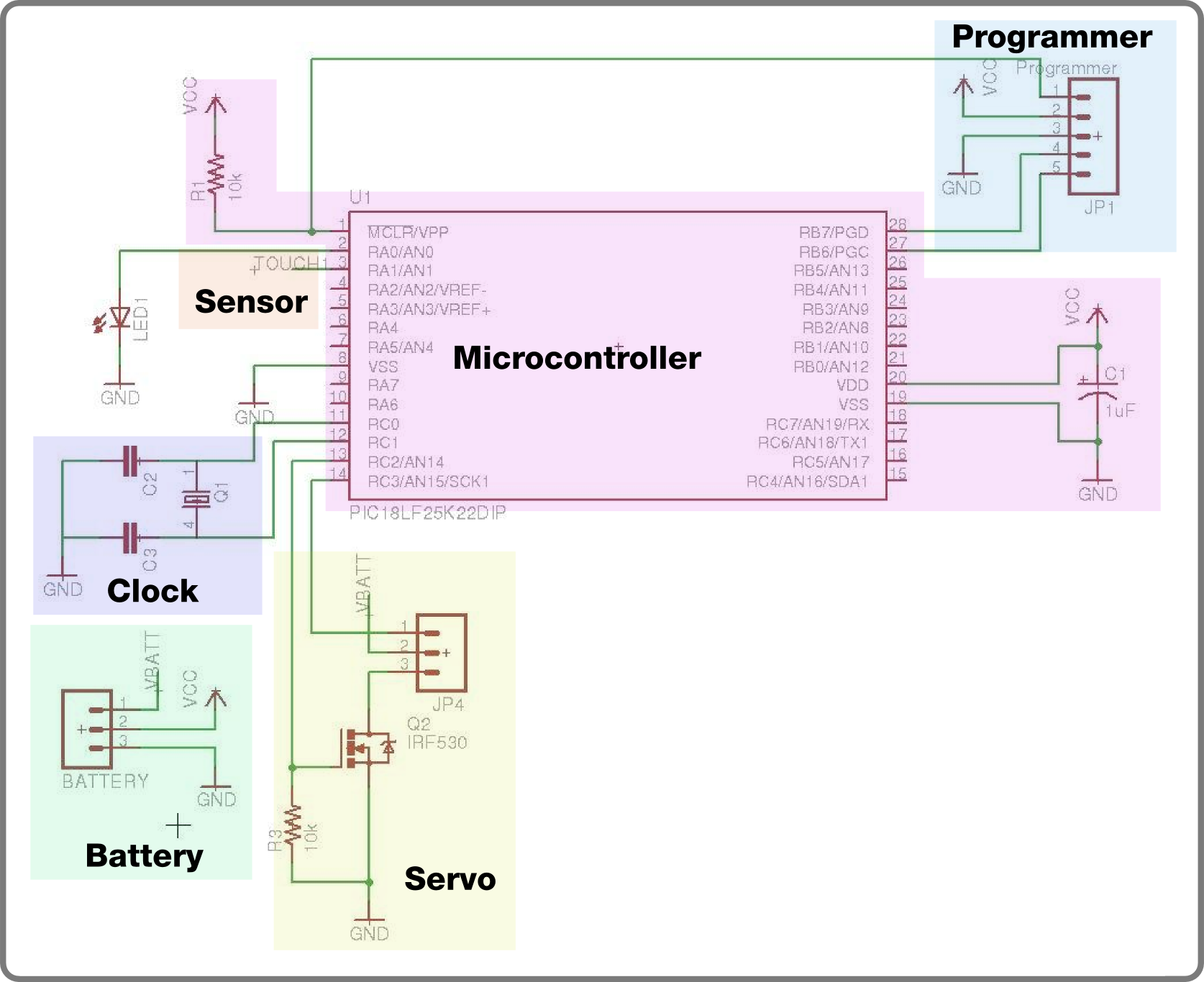
For the second build in the Make It Last Build Series, a robotic plant is being constructed. This week focuses on assembling the control circuit, which will be used in future weeks to animate the plant. The basic circuit...
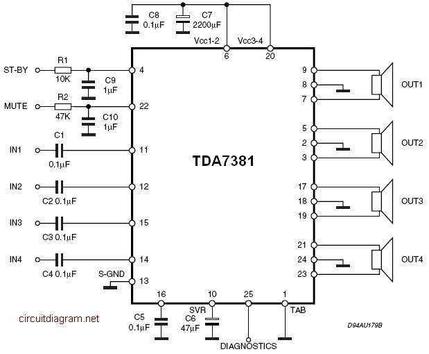
The TDA7381 is a Class AB audio power amplifier housed in a Flexiwatt25 package, specifically intended for car radio applications. This circuit can also be utilized for various other purposes. The fully complementary PNP/NPN output configuration enables a rail-to-rail...
This schematic illustrates an infrared (IR) transmitter circuit utilizing an integrated circuit (IC). The circuit employs the widely recognized NE555 timer IC, which operates as an astable multivibrator to generate a signal with a frequency of 38 kHz. The...
Figure A, B, and C illustrate the test rod end clip, with a positive power supply terminating test equipment. The B and C ends are connected in series with the load, where C represents the negative side of the...