
Automatic Street Light Controller Circuit

This automatic street light controller circuit utilizes an LDR to regulate lighting based on ambient light levels. The LDR is a crucial component; its resistance varies significantly depending on the light intensity. In darkness, the high resistance of the LDR allows a small current to flow, which is sensed by the LM741 operational amplifier. The LM741 is configured in a comparator mode, where it compares the voltage across the LDR (connected to the inverting input) with a reference voltage (connected to the non-inverting input). When the light level is low, the output of the LM741 is driven high, activating the transistor switch.
The transistor serves as a relay driver, providing sufficient current to energize the relay coil. When the relay is energized, it closes its contacts, allowing current to flow to the AC lamp, thus illuminating the area. Conversely, when sufficient light is detected, the resistance of the LDR decreases, resulting in a higher voltage at the inverting input compared to the non-inverting input. This causes the output of the LM741 to drop, turning the transistor OFF and deactivating the relay, which in turn cuts off power to the lamp.
The circuit is powered by a 9V battery, ensuring that it can operate independently of mains power. The design should include protection mechanisms such as a diode across the relay coil to prevent back EMF from damaging the transistor when the relay is turned OFF. The PCB layout should be designed to minimize noise and ensure reliable operation, with clear traces for the high-power AC connections and appropriate spacing to prevent arcing. The overall design is efficient and effective for automatic street lighting applications, ensuring lights are only on when needed, thereby conserving energy.This circuit is an automatic street light controller. Sensors used to detect changes in light is LDR (Light dependent resistor), the working principle of Light dependent resistor is exposed to light when the resistance value of LDR great, but if not exposed to light or dark then the resistance value of LDR. This circuit when the dark conditions (n ight) or the resistance value of LDR, a small electric current is passing, because the non-inverting reference voltage is greater than the inverting input voltage. So that the LM741 IC output value 1 ³, the transistor switches in the ON condition, the relay is also in the ON condition, so that the light is on.
Here is a schematic drawing of automatic street light controller: When light conditions (daylight) or LDR resistance value is small, a large electric current is passing. This is due to the inverting input voltage is greater than the non-inverting reference voltage, the LM741 IC output value 0 ³, the transistor in the OFF condition, the relay is also in the OFF state, so the lights went out.
To light using AC Lamp 220V 20watt. To source voltage of this circuit using a battery 9Volt. LDR (Light dependent resistor) should be placed on the affected light directly. here I also include a PCB (printed circuit board) of the automatic street light controller and you can also download it. 🔗 External reference
Related Circuits
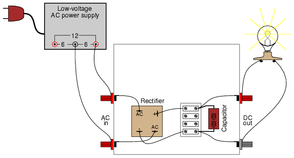
A bridge rectifier module is strongly recommended over building a bridge rectifier circuit using individual diodes. These modules are designed to be mounted on a metal heat sink. A metal enclosure is preferred over a plastic one due to...
The circuit diagram for a dynamic toy that produces eight sounds and five flashing lights is illustrated. It features the HFC3018 module, capable of generating eight distinct sounds, including step gunfire, aviation gunfire, game sight, telephone sight, bomb 1,...
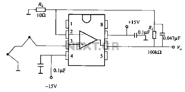
The OP07 is a low drift operational amplifier with a maximum voltage drift of 30 µV/°C and a maximum drift of 0.6 mV/V/°C. It features low noise characteristics with a maximum noise level of 0.6 pV/√Hz, offering ultra-stability with...
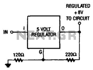
If locating an 8-V regulator proves difficult, a 5-V unit can serve as a replacement by connecting the regulator as illustrated here. In electronic circuits, voltage regulators are essential components that maintain a constant output voltage regardless of variations in...
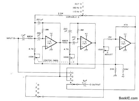
The circuit utilizing Optical Electronics 9803 operational amplifiers separates an audio frequency (AF) input signal into two outputs. The low-pass output allows frequencies from DC up to 10 Hz, while the high-pass output encompasses frequency content above 10 Hz,...
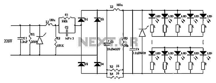
Circuits C1, R1, varistors, L1, and R2 form a filter circuit that includes a primary power supply capable of filtering out transient overvoltage inputs. The circuit also consists of C2 and R2, with additional components C3, C4, and L2....