
Automatic Switch Project 2

The pulsed infrared sensor system provides a reliable method for determining the location of trains on a layout, ensuring safe operation and efficient routing. The configuration includes a microcontroller that processes the signals from the PNA4602M infrared detectors. These detectors are sensitive to the specific pulsing frequency, allowing them to filter out unwanted infrared signals that may arise from environmental factors. The design emphasizes simplicity and effectiveness, utilizing readily available components such as the PICAXE microcontroller, which is programmed to emit the required pulsed signal.
The construction of the sensors involves precise placement of the infrared emitter and detector, ensuring they are aligned correctly across the track. The inclusion of a tantalum capacitor aids in stabilizing the voltage levels, contributing to the reliability of the readings. The output from the detectors can be used not only for monitoring train positions but also for activating various control mechanisms, such as relays for signaling or automated switch adjustments.
For layouts located indoors, the reliance on pulsed infrared sensors can be reduced, as ambient light can be more easily controlled. In such cases, the use of photo transistors can provide a simpler solution for detecting train presence through visible light. The versatility of the sensor system allows for adaptations based on specific layout conditions, making it a valuable tool for model railway enthusiasts seeking to enhance their control systems.The eyes of the switch control system allow the microcontroller`s "brain" to know where the trains are located on the layout. This insures that only one train is on the main line at a time and that the switches are set so that the train returns to the proper siding.
There are many ways to sense whether or not a train is at a particular spot on a layout. In 2005 I wrote a three part series for LSOL ( Garden Railway Sensors, Part I, Part II and Part III ) that explored a number of ways of sensing a train`s location. I finished up that series with a detailed description of what I feel is the best choice for most of our outdoor train sensing needs.
This is device is called a pulsed infrared sensor. I will briefly revisit it here and ask that you refer to the earlier articles for more detailed information. Pulsed infrared sensors are made up of several components. The most visible parts go on either side of a piece of track, the infrared emitter on one side and the infrared detector on the other.
When a train passes between them the beam of IR light is broken in much the same way that some automatic doors sense a customer`s presence. What really sets this sensor apart is that the devices operate with infrared light that is pulsed on and off at 38 kHz.
This means that the infrared emitter sends out bursts of IR 38, 000 times each second and the detector only reacts if it detects IR pulsing at that frequency. This is important because there are many sources of infrared light in and around our garden railroads.
These sources include fluorescent and other lighting devices but most of the extraneous IR comes from the sun. Pulsed IR sensors are not completely immune from the effects of direct sunlight but they perform better than most other technologies.
By the way, you use 38 kHz pulsed IR every time you use a TV`s remote control. The IR detector that we will use is a PNA4602M, a device with only three connections. One goes to +5 volts, one goes to ground and the output pin goes directly to an indicator, a transistor activated relay or, in our case, to the microcontroller. When the detector "sees" 38 kHz IR the output pin shows 0 volts and is said to be "low". When no IR is present it shows 5 volts, referred to as "high". This swing between 0 and 5 volts is easily detected by the microcontroller so that appropriate decisions can be made.
The sensors were constructed by drilling 3/32" holes near the tops of 2" x 4" x 3/4" blocks of wood. The emitter is glued into one and the detector into the other. In this photo of one of my prototypes the detector is on the near block and the emitter is on the one on the far side of the track. Wiring can be seen from the diagram below and the photo. Note that there is a 0. 1 mfd tantalum capacitor, the mustard colored device in the photo, between the positive and ground leads of the detector.
This helps to keep this very sensitive device from giving false readings. The three IR LEDs are connected to one of the output pins of the PICAXE that is programmed to generate the 38 kHz pulses that the PNA4602M detectors can sense. Each of the detector output pins go to an input pin on the PICAXE. One of these sensor units is placed just before the end of each block so that the engine breaks the IR beam as it nears the end of the block.
In the photo below you can see the IR detector side of sensor number 2. The emitter is behind the 0-4-0 locomotive. If a layout is indoors it is not necessary to use pulsed IR sensors as ambient infrared is less prevalent and more easily controlled. In such a situation simple photo transistors that are sensitive to visible light can be used. The phototransistors that I used are similar to ones that are available from The Electronic Goldmine (see: ).
These devices, shown below, are NPN transistors that allow current to flow between their emitter and detector when light falls on the lens on the face of the case. A se 🔗 External reference
Related Circuits
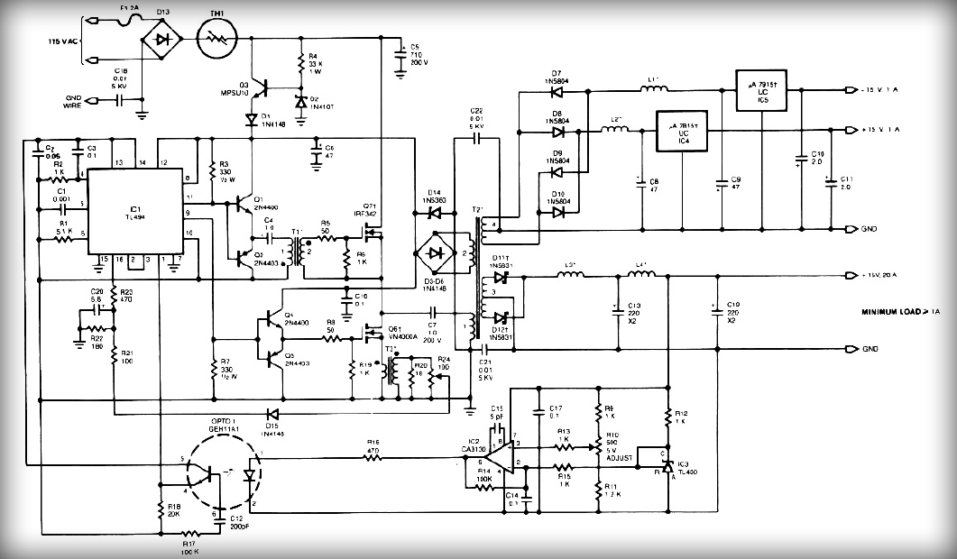
This power supply employs two VN400A 400-Volt MOSFETs arranged in a half-bridge configuration. The outputs provide +5V at 20A and +15V at 1A. Low-current outputs utilize three-terminal regulators, allowing for either 12 Volts or 15 Volts to be achieved...
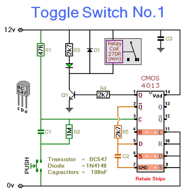
This circuit will activate and deactivate a relay with the press of a button. Any momentary push-to-make switch can be utilized. Pressing the button once will activate the relay, while pressing it a second time will deactivate the relay....
This circuit sequentially lights ten bulbs, first in one direction and then in the opposite direction, creating an appealing visual effect. Gates N1 and N2 form an oscillator, which serves as a clock for the BCD up/down counter CD4510...
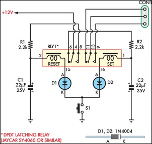
This circuit enables an SPST momentary pushbutton to function as a push-on push-off switch by utilizing a DPDT latching (bi-stable) relay. It was designed to allow a single pushbutton switch on the dashboard of a vintage car to provide...
This is a High Voltage switching device for driving coils and which have big impedance when it is switched off. It can be used in Back-EMF energy recovery tests, Newman coils electronic commutator. This device is driven by an...

Improve the power factor (PF) to enhance energy conservation in electrical equipment. With advancements in electronic technology, high-frequency active power factor correction (PFC) technology has been increasingly applied across various power systems. The switching power supply of large-screen color...