
Automatic telephone answering and ringtones indicator circuit diagrams

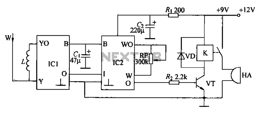
The loop circuit in an automatic telephone answering system is designed to detect incoming calls and activate the answering mechanism. This circuit typically consists of a series of components that work together to monitor the telephone line's status. When a call is received, the circuit detects the loop current, which is the flow of electric current through the telephone line.
Key components of the loop circuit may include a relay, which is used to switch the answering machine on or off, and a microcontroller that processes the signals received from the telephone line. The microcontroller can be programmed to recognize specific tones or signals, such as the ringing signal from an incoming call, and respond accordingly by activating the answering function.
In the context of a tone generator used for reverse automatic repair, the circuit may also incorporate a tone generator IC (integrated circuit) that produces specific audio frequencies. This is useful for testing and troubleshooting telephone lines, as it allows technicians to generate a test tone that can be sent through the line to verify its functionality. The tone generator can be activated by the same loop circuit, providing versatility in its application.
Overall, the design of the loop circuit must ensure reliable detection of incoming calls and proper operation of the answering system or tone generator, with careful consideration of component selection and circuit layout to minimize noise and interference. Check loop circuit for automatic telephone answering or tone generator for use reverse automatic repair.
Related Circuits
A circuit for an inductive burglar alarm is derived from a radio scanning detection circuit, which includes a signal processing circuit and an alarm circuit. The radar detection circuit module consists of components such as microwave emission, low-pass filtering,...
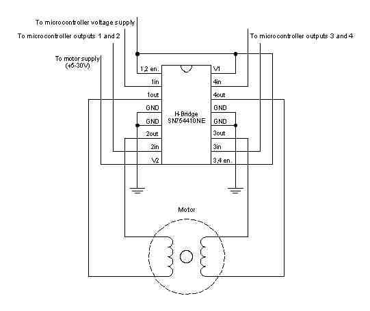
A stepper motor is a motor controlled by a series of electromagnetic coils. The center shaft has a series of magnets mounted on it, and the coils surrounding the shaft are alternately energized or de-energized, creating magnetic fields that...
AC level meters, such as VU meters, and DC level meters, such as signal meters, are used for measuring electrical signal levels. These devices feature a display consisting of nine red or green LEDs that represent the input level...
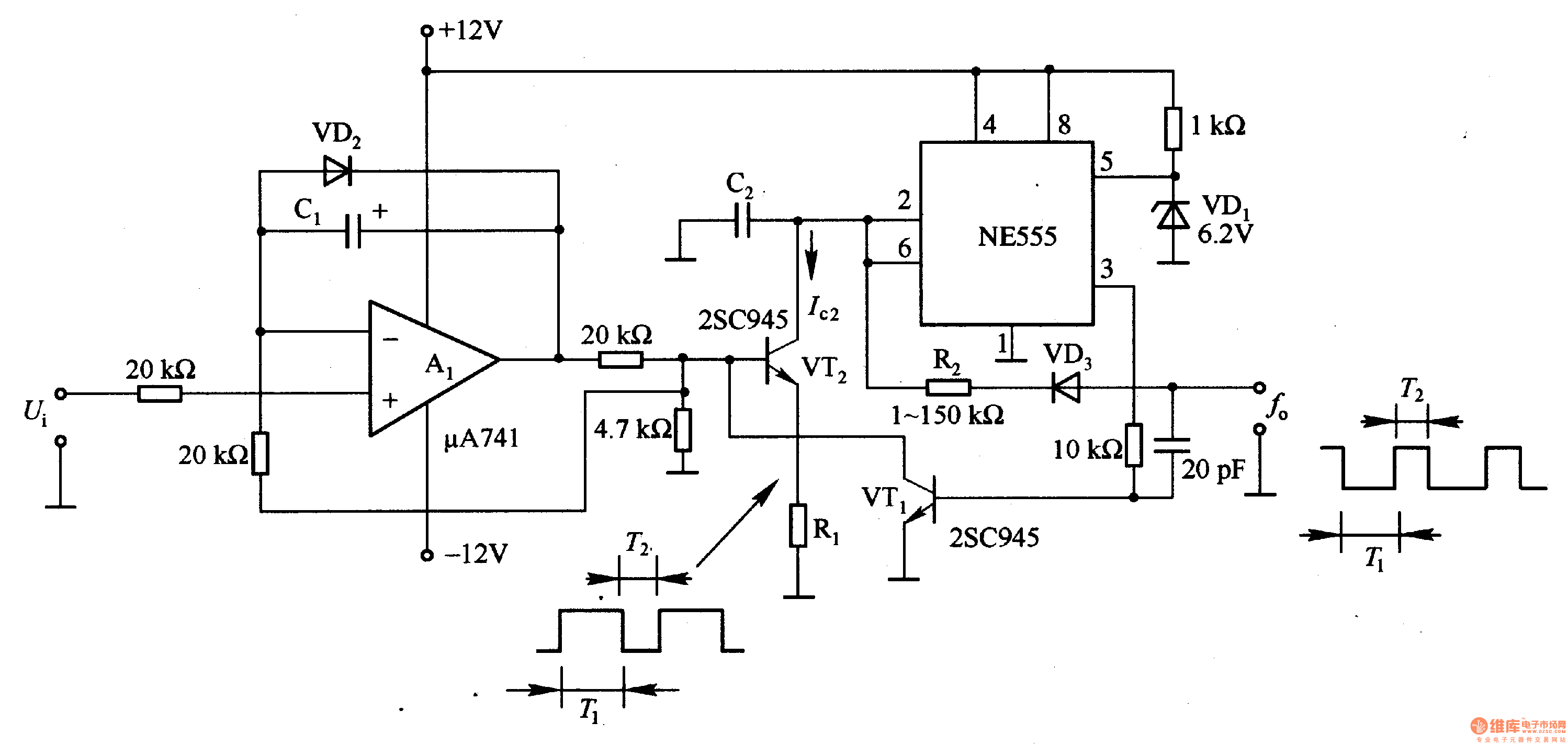
In the circuit, the oscillation frequency of the NE555 is controlled by VT2. When the output at pin 3 is low (during the T1 period), VT1 stops conducting, and VT2 begins to conduct with a current Ic2 flowing through...
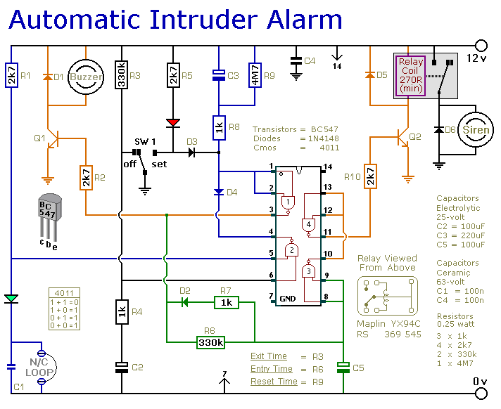
This is a simple single-zone burglar alarm circuit. Its features include automatic Exit and Entry delays and a timed Bell/Siren Cut-Off. It is designed to be used with the usual types of normally-closed input devices such as magnetic reed...
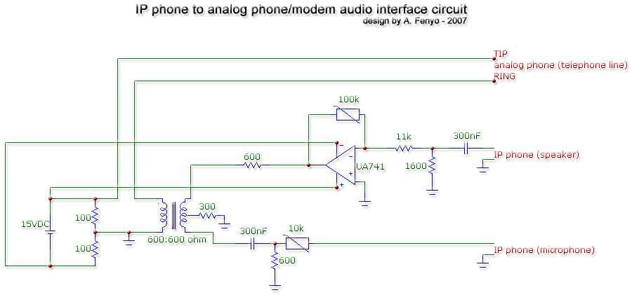
The transformer is a 600:600 ohm transformer, also referred to as a 1:1 ratio 600 ohm transformer. It has approximately the same number of turns on both the primary and secondary coils and is optimized for operation at a...