
Three-phase six-step motor control circuit diagram composed of MC33035
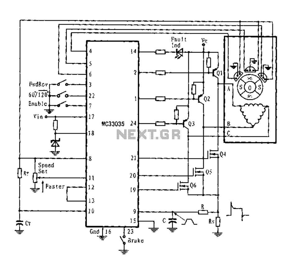
The three-phase full-wave six-step motor controller circuit is designed to efficiently manage the operation of an open-loop motor. The PNP Darlington transistors serve as the primary power switches, providing high current gain and facilitating the control of larger currents necessary for motor operation. The inclusion of N-channel power MOSFETs as lower power switches is critical due to their high efficiency and fast switching capabilities, which contribute to the overall performance of the circuit.
Each transistor within the circuit is equipped with parasitic clamping diodes. These diodes are essential for managing the inductive kickback generated by the stator coils during operation, allowing the energy to be returned to the power supply rather than dissipating as heat. This feature enhances the efficiency of the motor controller and prolongs the lifespan of the components.
The circuit's output configuration allows for flexibility in connecting the stator windings. By supporting both triangular and star configurations, the circuit can adapt to various motor designs and application requirements. The option to connect to a Y-neutral ground further enhances the circuit's versatility, enabling it to operate effectively under different electrical conditions.
In operation, at any rotor position, only one power switch from each totem pole is activated, ensuring that the circuit maintains optimal control over the motor. This selective switching allows for the efficient management of current flow through the stator windings, facilitating two-way or full-wave current operation. Such control is vital for achieving smooth motor performance and minimizing vibration.
To address the issue of leading edge spikes in the current waveform, which can lead to limiting errors and affect the performance of the motor, a peak RC filter is incorporated into the design. This filter effectively smooths out transient spikes, ensuring a more stable current detection input. The use of a low sense resistor (Rs) further assists in reducing these spikes, enhancing the reliability and accuracy of the current sensing mechanism within the circuit.
Overall, this three-phase full-wave six-step motor controller circuit is a sophisticated solution for driving open-loop motors, combining effective power management with adaptive output configurations and robust spike suppression techniques.Fig application circuit is a three-phase full-wave six-step driving an open loop motor controller circuit connection diagram. Wherein the power switching transistor Darlington PNP type, the lower power switching transistors are N-channel power MOSFET. Since each device contain a parasitic clamping diodes, which can power the stator inductive energy returned. The output can drive triangular connection or star connection of the stator, if using a separate power supply, but also to drive the Y-connected neutral ground.
At any given rotor position, the circuit shown in Figure 3 are the only one at the top and bottom power switches (belonging to different totem poles) is valid. Thus, through the rational allocation can switch the stator windings from the power supply to ground at both ends, and allows two-way or full-wave current.
Since the leading edge spikes usually occur in the current waveform, and will result in limiting errors. Therefore, the class can be suppressed by the peak RC filter in series with a current detection input.
Meanwhile, Rs low sense resistor also help reduce spikes.
Related Circuits

This alarm can be easily adapted for a 6-volt system, making it suitable for protecting classic bikes. With a standby current of zero, it will not drain the battery. The alarm features a timed siren output and automatic reset....
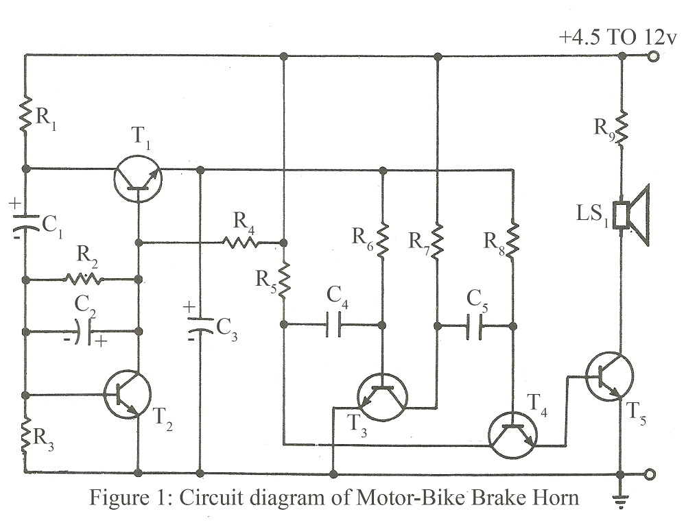
The circuit is designed to operate within a voltage range of 4.5V to 12V DC, or it can be directly connected to the brake point of a motorcycle. Resistor R7 should be replaced with a 1-ohm, 1/2W resistor when...

This keypad is designed for use with a modular burglar alarm system but can also be applied in various other applications. Pressing a single key will activate the relay, while entering a four-digit code of your choice will deactivate...

This three-band equalizer circuit functions as an active filter network for bass, mid, and high audio frequencies. It is built around the LM833 operational amplifier from National Semiconductors. The output of this three-way graphic equalizer is configured to be...
A PIR sensor is triggered when using a timer to wait for 2 seconds after the sensor is activated. Without the timer, the sensor operates as intended. The PIR sensor is connected to an ATMega328p microcontroller, which has three...

This temperature controller has a range of -50 to +150 °C and permits defrosting. R7, VR3, and R8 set the controller's trip point. SI initiates defrosting, and S2 cancels defrosting. VR1 and VR2 set the defrost temperature trip point....