
Temperature Controller With Defrost Cycle

The temperature controller circuit is designed to maintain a specified temperature range, specifically from -50 °C to +150 °C, making it suitable for various applications, including refrigeration and heating systems. The circuit is equipped with multiple resistors (R7, VR3, and R8) that allow for fine-tuning of the trip point, which is the temperature at which the controller activates or deactivates the connected device.
The initiation and cancellation of the defrosting process are controlled by switches SI and S2, respectively. This feature is particularly useful in refrigeration applications where frost build-up can hinder performance. The defrost temperature trip point is adjustable using variable resistors VR1 and VR2, providing flexibility in operation according to specific needs.
The LM134 thermal sensor (IC1) is integral to the circuit, providing accurate temperature readings. The output from the LM134 is buffered by one section of the quad op-amp IC3, ensuring that the signal is stable and suitable for further processing. The second section of IC3 operates as a Schmitt trigger, which helps eliminate noise and provides a clear transition between high and low states. This section also acts as a comparator for the defrost-cycle circuitry, ensuring that the defrost process is initiated and terminated at the correct temperatures.
For applications where a heater is preferred over a refrigeration unit, it is crucial to modify the circuit by omitting the final inverter in the base circuit of transistor Q1. This adjustment allows the controller to function appropriately with heating elements.
The circuit requires the use of LM7805 voltage regulators, which are essential for providing a stable 5 V output. It is critical to select LM7805 components that output between 4.95 V and 5.05 V to ensure proper operation of the entire circuit. Deviations from this voltage range could lead to malfunction or failure of the temperature control system. This temperature controller has a range of -50 to +150°C and permits defrosting. R7, VR3, and R8
set the controller"s trip point. SI initiates defrosting, S2 cancels defrosting. VR1 and VR2 set the defrost-temperature trip point. The LM134, IC1, is a thermal sensor. One section of IC3, a quad op amp, buffers the sensor"s output. The other section functions as Schmitt trigger and buffer for the normal-cycle circuitry and as a comparator for the defrost-cycle circuitry. you wish to control a heater rather than a refrigerator, omit the final inverter in Ql"s base circuit.
You must select LM7805s that have outputs between 4.95 and 5.05 V, or the circuit might not work.
Related Circuits
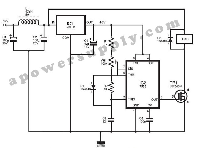
This DC power supply controller is regulated by pulse width modulation (PWM), which is generated by a circuit utilizing timer IC2 7555 according to a specific duty cycle formula. The described DC power supply controller employs a timer IC, specifically...
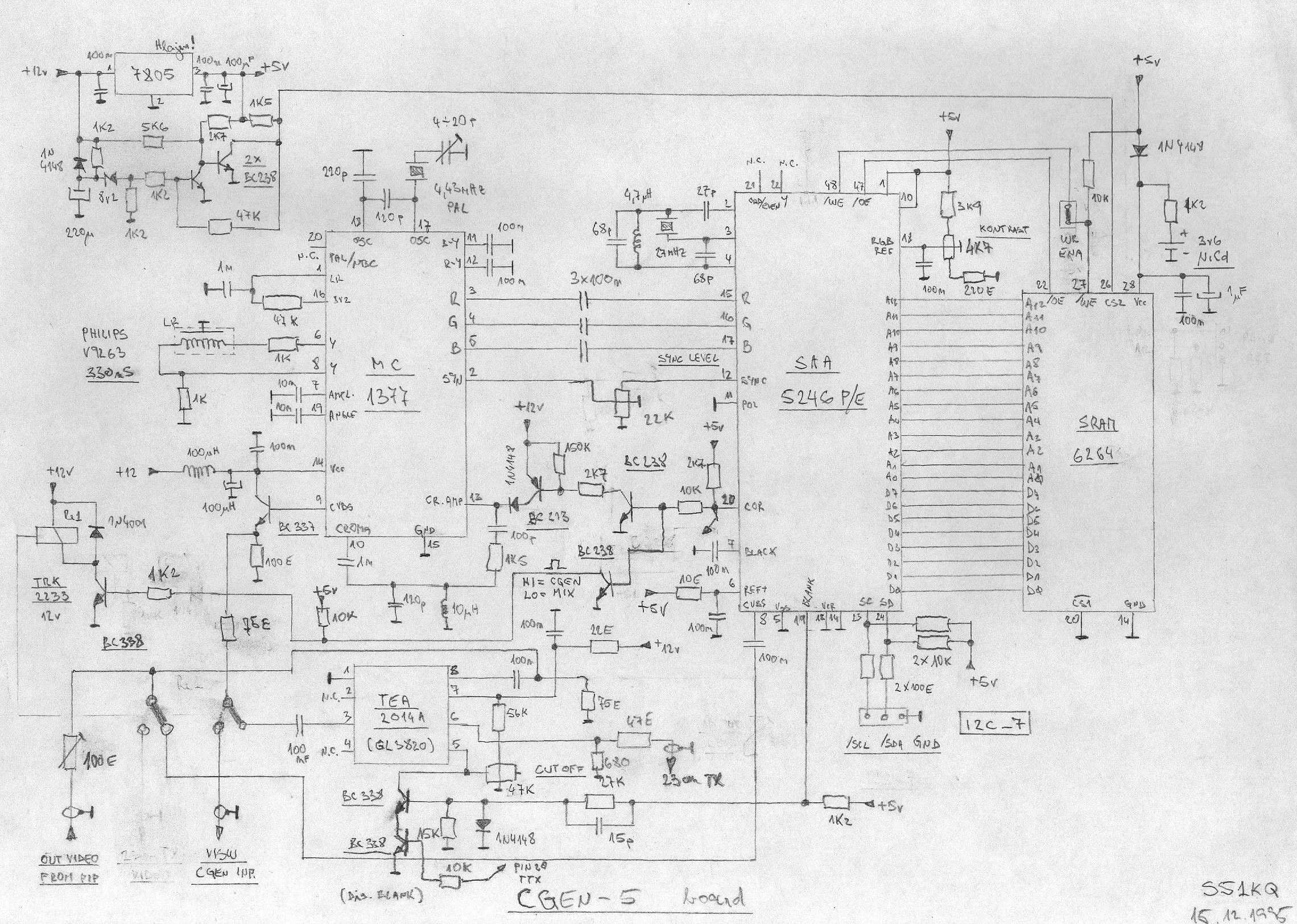
This is an image Schematic. No Description available. The provided input indicates that there is an image schematic without any accompanying description. In scenarios where a schematic is presented, it typically contains graphical representations of electronic components and their...
The following circuit illustrates a stepper motor controller. This circuit is based on the PIC16F84A integrated circuit. Features: a transistor is utilized to drive the motor. The stepper motor controller circuit employs the PIC16F84A microcontroller, which serves as the central...
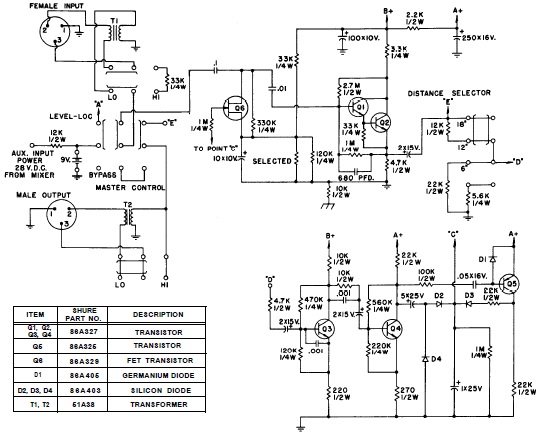
SHURE is an American corporation that manufactures consumer and professional audio electronics, including microphones, phonograph cartridges, and discussion systems. SHURE Incorporated is a well-established entity in the audio electronics industry, recognized for its innovative design and high-quality products. The company...
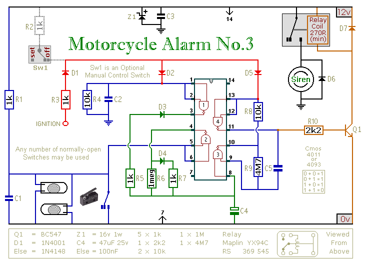
This circuit features an intermittent siren output and automatic reset. It can be operated manually using a key-switch or a hidden switch; but it can also be wired to set itself automatically when you turn-off the ignition. By adding...
The TRW-24G connector pins are quite small, approximately 1mm apart. To address this issue, an adaptor PCB has been ordered to convert the small connector of the RF module to a standard pin connector. The pin arrangement of the...