
2Y- connection two-speed motor contactor control one circuit
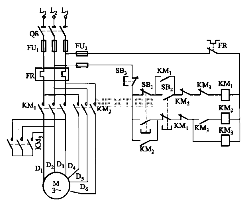
The circuit operates by utilizing a motor control setup that integrates multiple buttons to manage the speed and operation of the motor. The low-speed button (SBz) serves to initiate the motor at a reduced speed, ensuring a gradual start-up and minimizing mechanical stress. When SBz is pressed, it completes a circuit that energizes the relay KMa, which subsequently engages the first contact of the stator winding. This initial activation is crucial for establishing the motor's operational state.
Once KMa is engaged, the next relay, KMz, is activated, allowing the motor to draw power efficiently. The sequential activation of these relays is essential for controlling the motor's speed and preventing sudden surges in current. The design incorporates a safety feature to mitigate the risk of damage to the main contact KM3, which could occur if the motor were to receive excessive current during start-up. By ensuring that the relays engage in a controlled manner, the circuit protects the components from potential burnout.
In addition to the operational buttons, the circuit includes a stop button (SB3), which provides a means to halt the motor's operation safely. This button interrupts the power supply to the motor, allowing for immediate cessation of operation when required. The overall design of this circuit emphasizes reliability and safety, making it suitable for applications where motor control is critical. The careful arrangement of the relays and the operation buttons ensures that the motor can be operated effectively across different speed settings while maintaining protection against electrical faults. Circuit shown in Figure 3-96. Figure, SBz is running at low speed button, SBi as the high-speed operation button. SB3 for the stop button. In this circuit, a motor connected in to shape when 2Y, first contact the center point of the stator winding KMa turned, then KMz it was electric pull, power. This can be avoided when the power is turned on, due to excessive current burn KM3 main contact.
Related Circuits
An annual listing of the watermelon season reveals that many individuals lack the intuitive judgment to differentiate between raw and cooked watermelon. This often leads to unnecessary disputes regarding the classification of the fruit. A proposed solution is the...
This circuit is designed to demonstrate high frequency and high voltage, capable of producing approximately 30kV, depending on the transformer utilized. It is cost-effective and straightforward to construct, primarily using a standard TV flyback transformer. This circuit can power...
This circuit illustrates a remote control system utilizing a radio telephone circuit diagram. Features include the ability to switch appliances from any distance, overcoming various limitations. The remote control circuit employs radio frequency (RF) technology to facilitate wireless communication between...
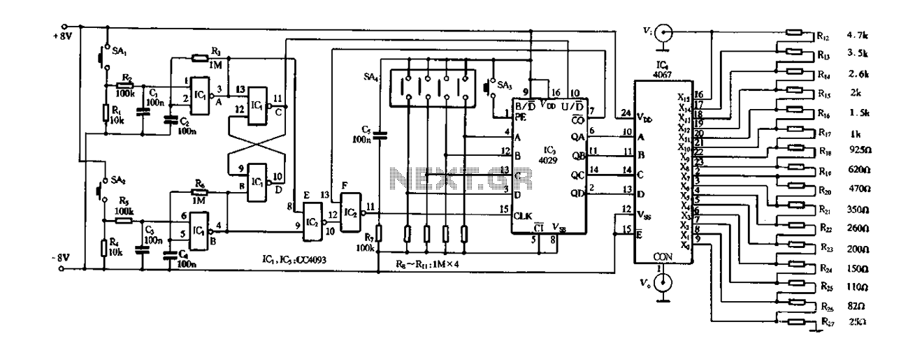
Figure 4-14 illustrates a digital integrated circuit featuring 16 preset potentiometers for Siniperca electronic circuits. The circuit comprises three main components: an input controller, a presettable counter, an analog electronic switch, and a resistor network. It includes a push-button...
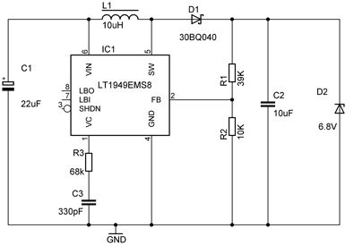
A portable phone charger designed for a Siemens mobile phone has been updated to include a printed circuit board (PCB), a USB connector, and enhanced current capabilities. The new charger utilizes a step-up converter based on the TPS61032, which...
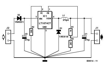
This 3-volt car adapter circuit is based on a standard LT1074CT switching regulator IC. The schematic shows the LT1074CT used as a positive step-down regulator. The 3-volt car adapter circuit employs the LT1074CT, which is a high-efficiency switching regulator capable...