
Remote Control Using Radio Telephone

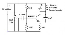
The remote control circuit employs radio frequency (RF) technology to facilitate wireless communication between a transmitter and a receiver. The transmitter typically consists of a microphone, RF oscillator, and a modulator. The microphone captures audio signals, which are then converted into electrical signals. The RF oscillator generates a carrier wave, and the modulator combines the audio signal with the carrier wave for transmission.
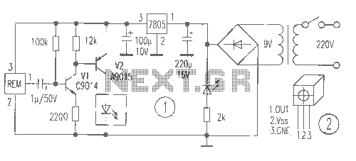
On the receiving end, the circuit includes an RF receiver, which demodulates the incoming signals to extract the original audio information. This signal can then be used to control various appliances, such as lights or motors, by interfacing with a relay or a microcontroller. The relay acts as a switch, enabling or disabling the power to the connected appliance based on the received command.
The range of the remote control system can be influenced by factors such as the power output of the transmitter, the sensitivity of the receiver, and environmental conditions. Antennas play a critical role in enhancing the transmission and reception quality, with suitable designs ensuring optimal performance.
In summary, this remote control circuit diagram represents a practical application of radio frequency technology, allowing users to operate devices wirelessly from considerable distances, thereby providing convenience and flexibility in various settings.This circuit shows about Remote Control Using Radio Telephone Circuit Diagram. Features: used to switch appliances from any distance, overcoming .. 🔗 External reference
Related Circuits
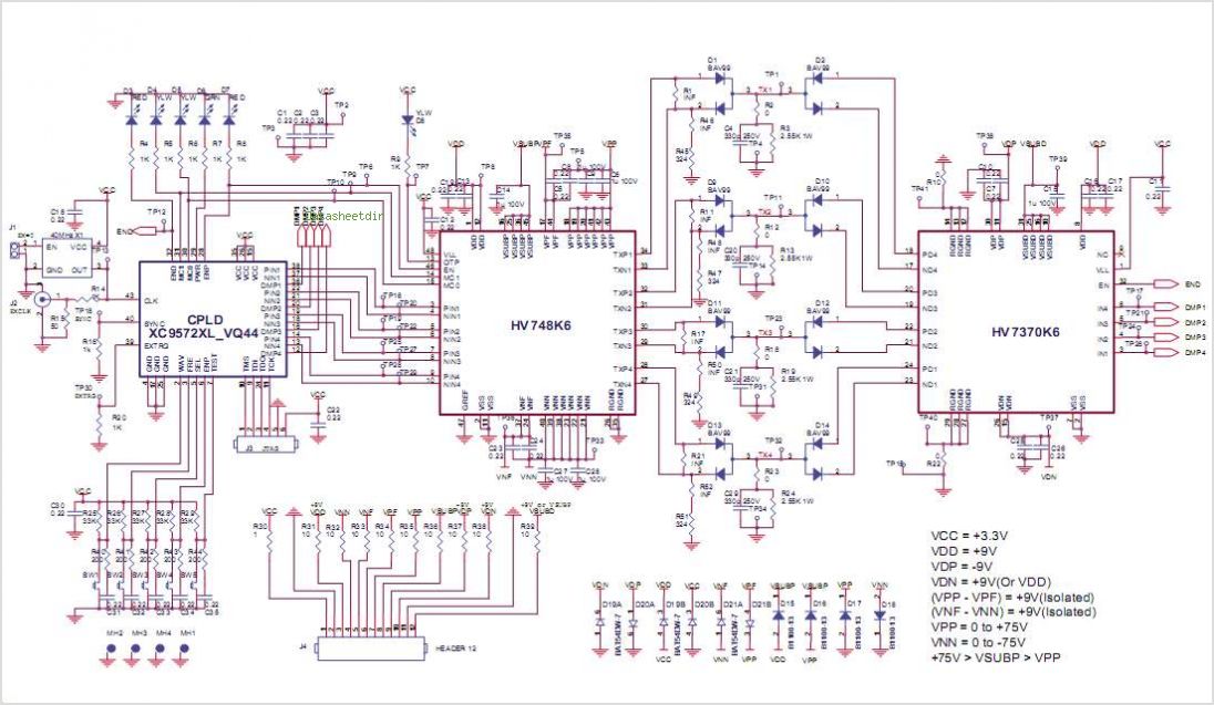
Many TOPSwitch TOP223 flyback power supply applications require two or more outputs to supply a variety of secondary circuits. Typical consumer applications of these multiple output converters include televisions and related products such as set-top decoders and video cassette...
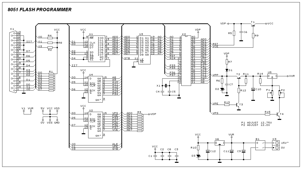
This programmer was designed to be flexible, economical, and easy to build. The programmer hardware utilizes standard TTL series parts, and no special components are used. The programmer is interfaced with the PC parallel port, and there are no...
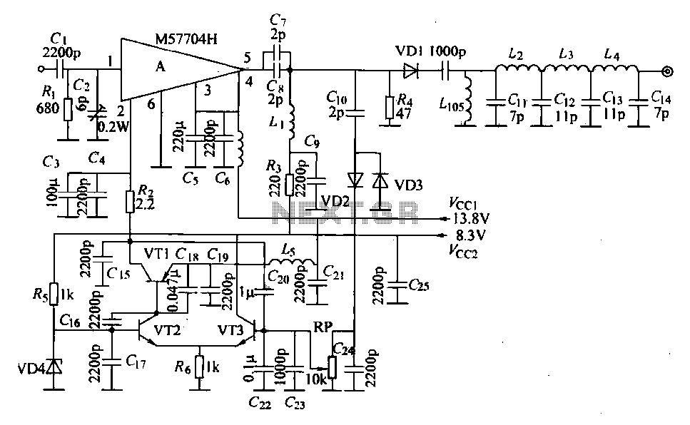
The FM radio transmitter is a high-frequency amplifier circuit that utilizes the Mitsubishi frequency set, specifically the M57704H discharge path. It operates within the frequency range of 457-458 MHz and has a transmission power of 5 watts. As illustrated...
This circuit is designed to attenuate signal frequency, with a customizable range from 1 to 40 dB. For UHF band usage, it should be enclosed within a shielded frame, and capacitors C1 to C3 should be appropriately selected. The...

This Project Automatic Room Light Controller with Visitor Counter using Microcontroller is a reliable circuit that takes over the task of controlling the room lights as well as counting the number of persons/visitors in the room very accurately. When...
The receiver provides two TV signals, one for the living room and another for the bedroom, along with a satellite receiver. Watching television in the bedroom is convenient in Taiwan; however, when watching television in the living room, it...