
Universal motor speed control
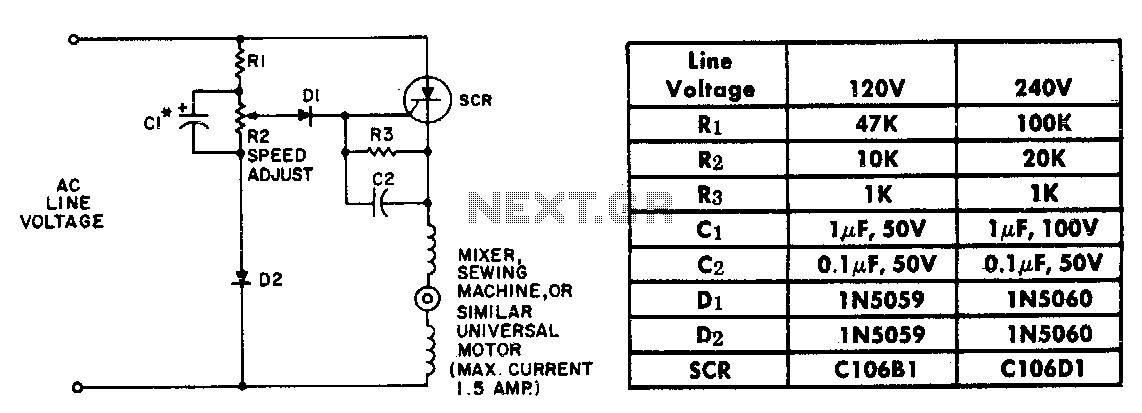
The described circuit employs a resistor-capacitor (RC) network consisting of resistors R1 and R2, and capacitor C1, which collectively create a ramp voltage signal. This ramp voltage is essential for modulating the control of a motor's speed, particularly in applications where load variations are common. The speed-setting potentiometer R2 plays a critical role in adjusting the amplitude of the reference voltage, allowing for fine-tuning of the motor's operational characteristics.
The interaction between the ramp voltage and the motor's counter emf is crucial for effective motor control. As the motor load increases, resulting in a reduction of counter emf, the ramp voltage triggers the SCR at an earlier point in the AC cycle. This early triggering increases the voltage applied to the motor, compensating for the drop in speed caused by the heavier load.
The choice of the C106 SCR is significant due to its low trigger current requirement, which allows the circuit to utilize a flat top reference voltage. This design choice enhances the feedback gain, providing a more stable and responsive control mechanism. The flat top reference voltage contributes to improved speed regulation, ensuring that the motor can maintain its desired speed despite fluctuations in load conditions.
In summary, the combination of the RC network, speed-setting potentiometer, and SCR provides an efficient method for controlling motor speed, with particular attention to maintaining performance under varying load conditions. The overall circuit design emphasizes reliability and precision, making it well-suited for applications requiring consistent motor operation.The resistor capacitor network R1-R2-C1 provides a ramp-type reference voltage superimposed on top of a dc voltage adjustable with the speed-setting potentiometer R2. This reference voltage appearing at the wiper of R2 is balanced against the residual counter emf of the motor through the SCR gate.
As the motor slows down due to heavy loading, its counter emf falls, and the reference ramp triggers the SCR earlier in the ac cycle More voltage is thereby applied to the motor causing it to pick up speed again. Performance with the C106 SCR is particularly good because the low trigger current requirements of this device allow use of a flat top reference voltage, which provides good feedback gain and close speed regulation. 🔗 External reference
Related Circuits
The proximity detector detects the movement of PC board pieces as the wheel rotates, generating an output signal with a clear transition between high and low voltage levels, making it suitable for triggering counting or processing circuits. Following this...
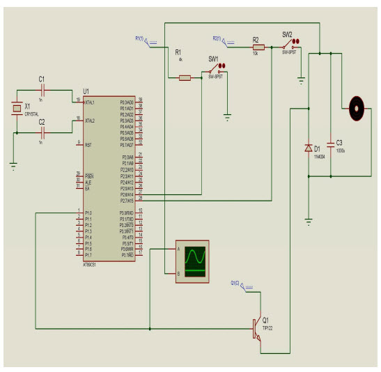
The objective of this project is to control the speed of a DC motor. The primary benefit of utilizing a DC motor is the ability to modify the Speed-Torque relationship to nearly any desired form. To facilitate speed control,...
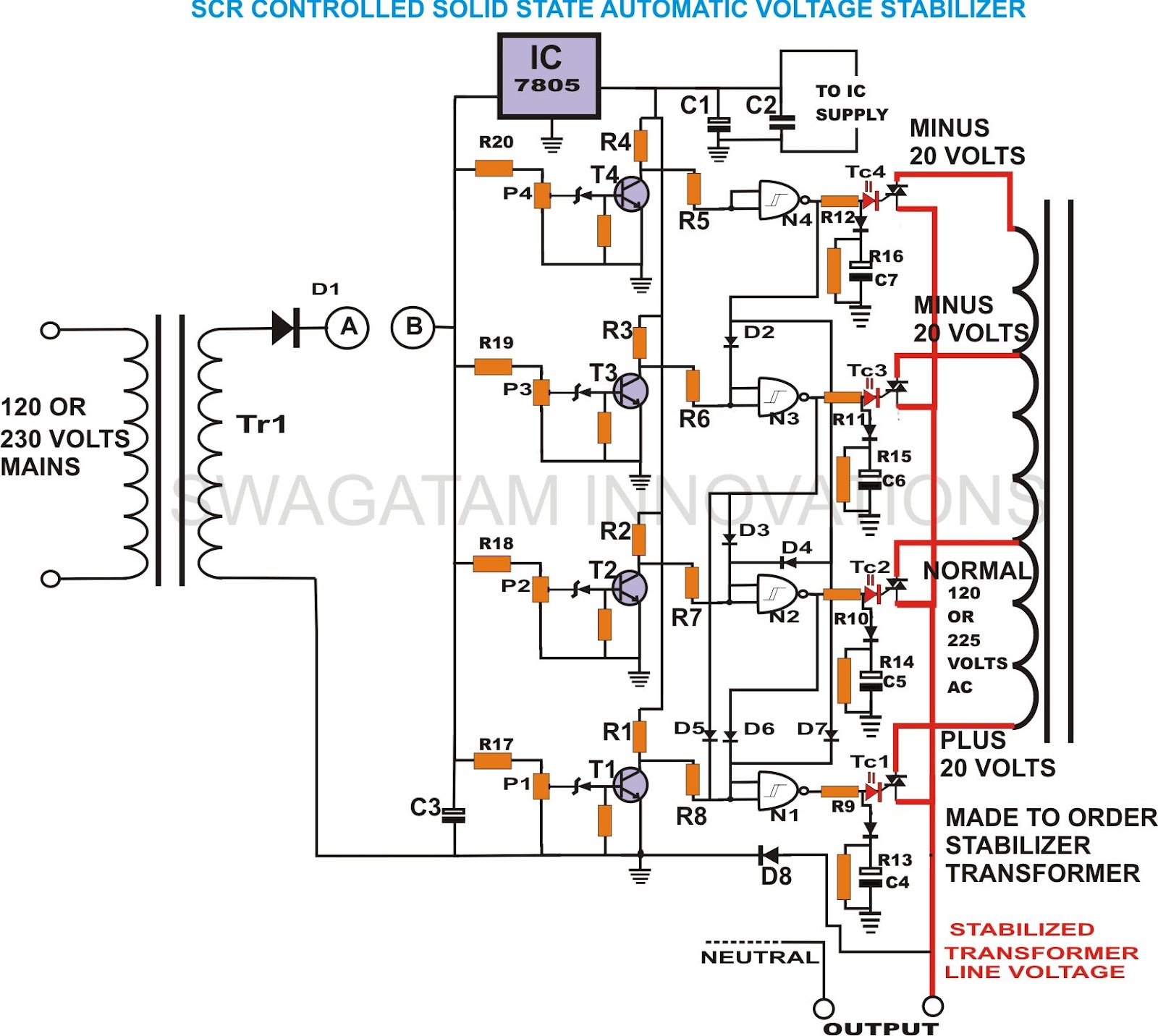
This unique and hard-to-find triac-controlled AC voltage stabilizer circuit has been specifically designed for efficient voltage stabilization. With a solid-state design, the voltage switching transitions are smooth, resulting in minimal wear and tear. The proposed circuit provides four-step voltage...
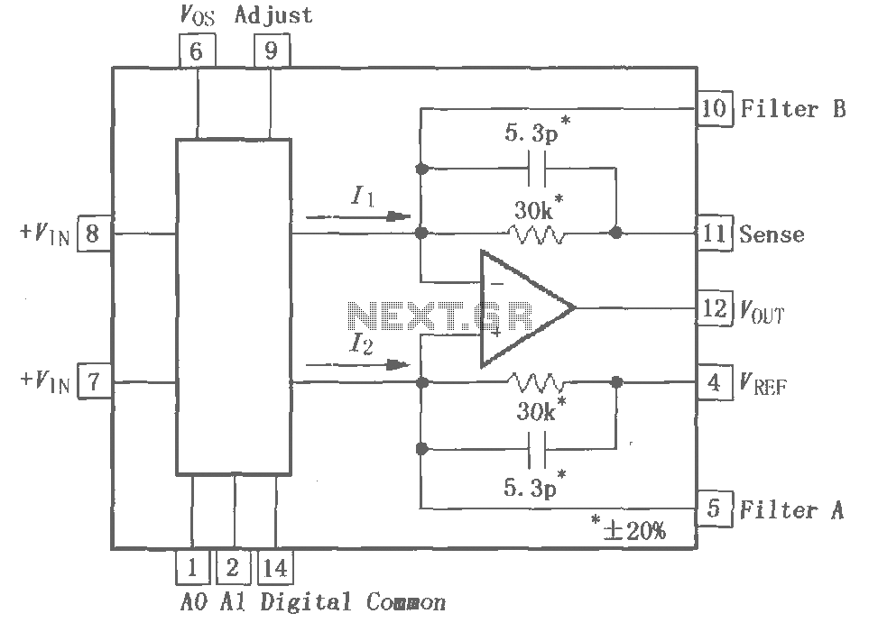
The PGA202 is a digitally controlled programmable gain amplifier with gain settings of G = 1, 10, 100, and 1000. The PGA203 offers gain settings of G = 1, 2, 4, and 8. Both amplifiers are compatible with CMOS...
Automatic Gain Control (AGC) is a circuit design that maintains a consistent level of amplification for sound or radio frequency signals. If the signal is too low, the AGC increases the gain to ensure the output remains at a...
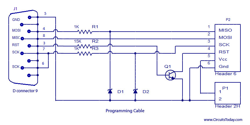
ISP programmer with circuit diagram for AVR Atmega32 microcontroller. This ISP burner circuit is an adaptation of the Pony programmer and uses PonyProg software. The ISP (In-System Programming) programmer designed for the AVR Atmega32 microcontroller allows for programming the microcontroller...