
build solid state scrtriac controlled

The triac-controlled AC voltage stabilizer circuit operates by continuously monitoring the input voltage and adjusting the output accordingly through a series of triacs and transistors. The circuit employs a feedback mechanism where transistors T1 to T4 are configured to detect voltage levels and activate the corresponding triac based on the voltage range. Each triac is responsible for connecting the output to a specific tap on the transformer, allowing for precise voltage control.
The design incorporates a transformer with multiple taps, which provides different voltage levels. As the input AC voltage fluctuates, the circuit dynamically selects the appropriate tap to maintain a stable output voltage. This is achieved by the rapid switching capabilities of the triacs, which can respond within milliseconds, ensuring that the output remains stable even with significant variations in input voltage.
The circuit is built around a general-purpose PCB, making it accessible for those with intermediate electronics skills. Key components include the triacs, transistors, resistors, capacitors, and the transformer. Proper selection and sizing of these components are critical to ensure reliable operation and safety. It is essential to follow the schematic closely during assembly to prevent misconfigurations that could lead to circuit failure or hazards.
Given the nature of the circuit, it is imperative to implement safety precautions. The circuit operates at mains voltage, which poses a risk of electric shock. Therefore, adequate insulation and protective measures should be in place during both assembly and operation. It is advisable to test the circuit in a controlled environment and to use equipment such as an auto transformer and a digital multimeter for performance verification, allowing for adjustments and ensuring the output voltage remains within desired parameters.This one of its kind and hard to find triac control AC voltage stabilizer circuit has been designed specifically just for you. Being solid state in design, the voltage switching transitions are very smooth with minimum wear and tear, resulting in efficient voltage stabilization.
Discover the whole construction procedure of this unique, solid state mains voltage stabilizer. The proposed circuit of a triac controlled AC voltage stabilizer will provide an excellent 4 step voltage stabilization to any appliance at its output. With no moving parts involved its efficiency is further enhanced. Find out more of this silent operator: power guard. The circuit of an automatic voltage stabilizer discussed in one of my previous articles, though useful, due to its simpler design, does not have the capability of controlling the different levels of varying mains voltages discretely.
The proposed idea though not tested, looks pretty convincing, and if the critical components are properly dimensioned, should work as expected. The present circuit of triac controlled AC voltage stabilizer is outstanding in its performance and is almost an ideal voltage stabilizer in every respect.
As usual the circuit has been exclusively designed by me. It is able to control and dimension the input AC mains voltage accurately through 4 independent steps. The use of triacs make it sure that the changeovers are quick (within 2 mS) and with no sparks or transients usually associated with relay type of stabilizers.
Also since no moving parts are employed, the entire unit becomes completely solid state and almost permanent. CAUTION: EACH AND EVERY POINT OF THE CIRCUIT PRESENTED HERE MAY BE AT AC MAINS POTENTIAL, THEREFORE EXTEMELY DANGEROUS TO TOUCH IN SWITCHED ON POSITION.
UTMOST CARE AND CAUTION IS ADVISED, USE OF A WOODEN PLANCK UNDER YOUR FEET IS RECOMMENDED. NEWBIES PLEASE KEEP AWAY. Transistors T1 to T4 are all arranged to sense the gradual rise in the input voltage and conduct one after the other in sequence as the voltage rises and vice versa. Thus, as the input voltage rises the gates respond to the transistors and their outputs subsequently become logic hi one after the other making sure that the previous gate`s output is shut OFF and vice versa.
The logic hi from the particular buffer is applied to the gate of the respective SCR which conducts and connects the relevant hot line from the transformer to the external connected appliance. As the voltage rises, the relevant triacs subsequently select the appropriate hot ends of the transformer to increase or decrease the voltage and maintain a relatively stabilized output.
The construction of this triac control AC power guard circuit is simple and just a matter of procuring the required parts and assembling them correctly over a general PCB. It is pretty obvious that the person who is attempting to make this circuit knows a bit more than just the basics of electronics.
Things may go drastically wrong if there is any error in the final assembly. Assuming that an output supply of 12 volts from TR1 corresponds to 225 volts input supply, through calculations we find that it will produce 9 volts at an input of 170 volts, 13 volts will correspond to 245 volts and 14 volts will be equivalent to an input of approximately 260 volts. You may verify the performance of the system by supplying a varying input AC through an auto transformer and checking the output using a digital multimeter.
🔗 External reference
Related Circuits
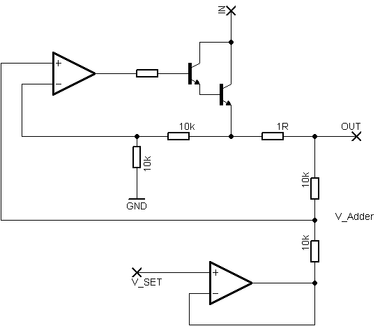
Rsense will cause Q2 to conduct when a threshold of approximately 0.65V is reached. Rbias will determine the extent of this limitation, although this aspect remains unclear. Particularly, if Rsense is positioned on the high side, simply activating Q2...
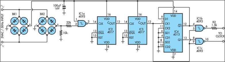
Quartz clocks, which have dominated timekeeping for the past 20 years, have one issue: their errors, although slight, are cumulative. Quartz clocks operate based on the piezoelectric effect of quartz crystals, which oscillate at a precise frequency when subjected to...
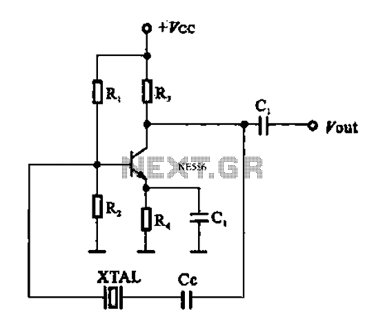
A series resonant circuit utilizing a crystal oscillator is illustrated. The crystal impedance reaches a minimum value at the series resonance frequency, resulting in a significant feedback amount. The crystal tuning capacitor (Cc) can slightly adjust the resonance frequency...
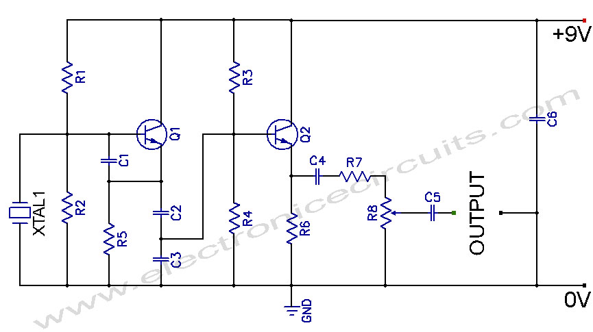
Crystal Controlled Oscillator Circuit. This general-purpose signal source is highly effective in signal-tracing applications. The output level is adjustable. The crystal-controlled oscillator circuit is designed to provide a stable and precise frequency output, which is essential for various electronic applications,...
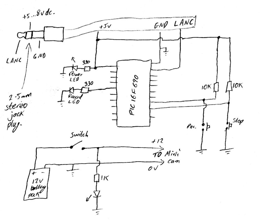
Inexpensive PIC-controlled helmet camera utilizing Sony LANC, suitable for extreme sports. This guide will demonstrate how to create an affordable helmet camera. The proposed electronic schematic involves a PIC microcontroller interfaced with a Sony LANC (Local Application Control Bus) to...
The circuit depicted in Figure 3-121 illustrates the key component of an electromagnetic holding brake, which consists of an electromagnetic brake solenoid primarily made up of two parts: the iron core and the shoe brake components. When power is...