
A discrete transistors from the current control circuit diagram of the way
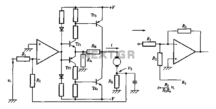
The discrete transistor current control circuit is designed to regulate the flow of current through a load by utilizing a transistor as the primary control element. This circuit typically consists of a few key components: a power supply, a load (which could be a resistor, motor, or LED), a transistor (often a bipolar junction transistor or MOSFET), and a control mechanism, which may include a potentiometer or a fixed resistor for setting the desired current level.
In operation, the circuit begins with the power supply providing voltage to the load. The transistor acts as a switch or amplifier, allowing current to flow through the load when the base (or gate, in the case of a MOSFET) is activated by a control signal. The amount of current flowing through the load is determined by the voltage applied to the base/gate of the transistor, which adjusts the transistor's conductivity.
A feedback mechanism may also be incorporated into the circuit to enhance stability and accuracy. This can be achieved by using a resistor in series with the load to sense the current, feeding a portion of the current back to the base/gate of the transistor. This feedback loop helps maintain the desired current level despite variations in load resistance or supply voltage.
The schematic representation of this circuit typically includes the power supply voltage source, the load, the control resistor or potentiometer, the transistor symbol indicating its type, and any additional components such as capacitors for filtering or diodes for protection against reverse polarity.
Overall, this discrete transistor current control circuit is a fundamental building block in electronic design, enabling precise control of current in various applications, from simple LED drivers to complex motor control systems.A discrete transistors by the current control circuit diagram of the way
Related Circuits
The laser-pointer detection circuitry is capable of identifying when a laser light is directed at a specific photosensor. If the laser targets the top sensor, the comparator chip outputs a high signal. Conversely, if the laser is aimed at...
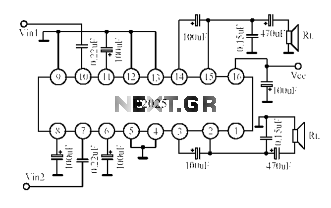
The D2025 is a dual audio power amplifier circuit designed as a stereo audio power amplifier integrated circuit. It comes in a DIP16 package and is applicable for various portable devices, such as tape recorders or portable stereo systems....
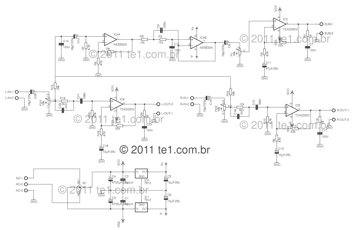
This circuit is a complete application for a 2.1 amplifier system, featuring two satellite speakers for TDA and one subwoofer. It is commonly used in commercial applications to enhance the audio output of computers using a stereo amplifier along...
This page will be updated as material becomes available. This new system will essentially replace the original BCD design, which was created by WB6IGP and N6IZW and was featured in the ARRL UHF/Microwave Project Manual. Their work was later...
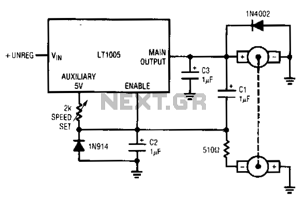
This circuit utilizes a tachometer to generate a feedback signal that is compared to a reference provided by the auxiliary output. Upon power application, the tachometer output is initially zero, allowing the regulator output to activate and supply current...
Most universal radio receivers have a very wide bandwidth that is not particularly suitable for radio amateurs. The better models with narrower bandwidth are almost a... Universal radio receivers are designed to operate over a broad frequency range, making them...