
Two electric motors or electrical interlocking control circuit
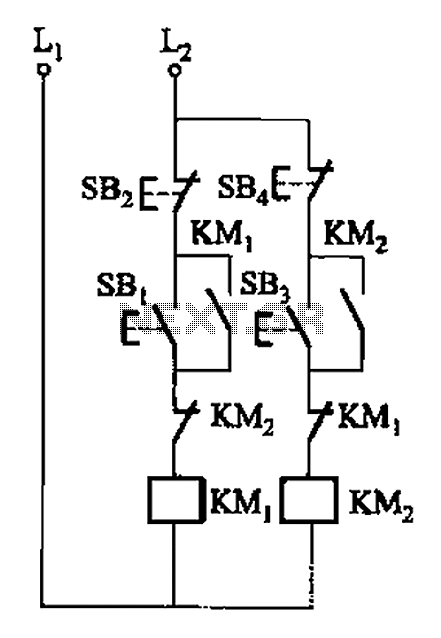
The circuit design facilitates the interlocking operation of two electric motors, referred to as Motor A and Motor B, ensuring that both motors can operate simultaneously without causing electrical faults or mechanical interference. The interlock control system is achieved through the use of normally closed contacts, which are integrated into the coil circuit of each motor.
In this configuration, the normally closed contacts are connected in series with the coils of the motors. When Motor A is energized, the current flows through its coil, causing it to operate. However, the normally closed contact associated with Motor B remains closed, allowing the current to flow to Motor A while preventing Motor B from being activated simultaneously. This arrangement ensures that if one motor is running, the other cannot be activated, thereby preventing potential overload or mechanical failure.
The circuit can be designed using relays or contactors that feature normally closed contacts. Each motor coil is connected to its respective relay, and the relay contacts are wired to form an interlock. This means that when one relay is energized, it opens the circuit for the other relay, effectively preventing both motors from running at the same time.
Additionally, this configuration can be enhanced with safety features such as overload protection and emergency stop buttons. These components can be integrated into the circuit to provide further reliability and safety during operation. The interlock control system is particularly useful in applications where motors must not operate simultaneously due to load constraints or mechanical coupling, ensuring a safe and efficient operational environment.A, B and two electric motors (or electronic) allowed simultaneous operation (interlock control). The two motors can (or electronic) of the respective contact normally closed co ntacts in series with each other interchangeably coil circuit,
Related Circuits
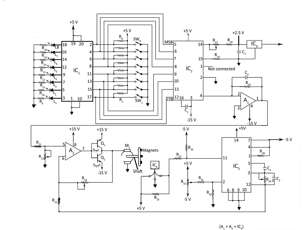
Various techniques can be employed to control the speed of a DC motor, including phase-locked-loop principles, digital inputs, or analog inputs. Additionally, the motor's speed can be monitored using LED or LCD displays. The digital DC motor speed controller...
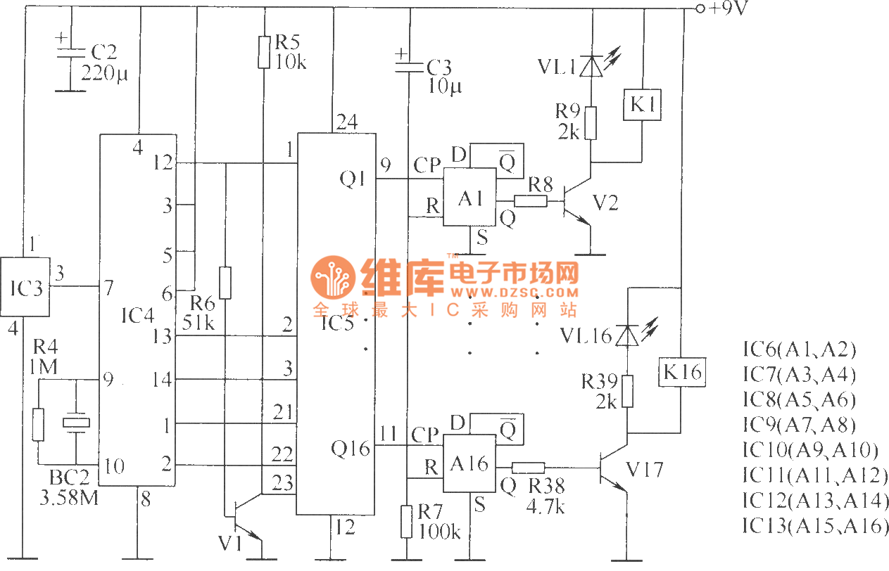
The wireless remote control transmitter circuit consists of control buttons S1 to S16, resistors R1 to R3, a capacitor C1, a regulator diode VS, a crystal oscillator BC1, and DTMF encoder integrated circuits IC1 and IC2. The circuit components...
The power amplifier Hi-Fi OCL 120W RMS is designed to operate effectively when paired with a suitable power supply circuit and 8-ohm speakers. This circuit exclusively utilizes transistors without any integrated circuits, resulting in a clean sound output. The...
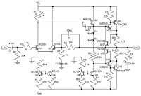
To configure the amplifier, set resistor R1 to its maximum value and resistor R12 to zero. After this adjustment, power on the amplifier. Adjust R1 until the measured output offset is between 30 mV and 100 mV. Once this...
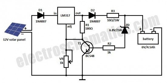
This is a solar charger circuit designed to charge Lead Acid or Ni-Cd batteries using solar energy. The circuit captures solar energy to charge the batteries. The solar charger circuit typically consists of several key components, including a solar panel,...
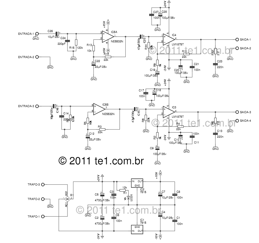
The LM1875 delivers 20 watts into a 4 or 8-ohm load on ±25V supplies. Using an 8-ohm load and ±30V supplies, over 30 watts of power may be delivered. The amplifier is designed to operate with a minimum of...