
Wireless remote control switch circuit 5

The wireless remote control transmitter circuit is designed to facilitate the transmission of control signals over a distance, typically using infrared or radio frequency technology. The control buttons S1 to S16 allow the user to input commands, which are processed by the DTMF encoder integrated circuits (IC1 and IC2). These encoders convert the button presses into a series of dual-tone multi-frequency signals, which are then transmitted wirelessly.
Resistors R1 to R3 serve various functions, including current limiting for the control buttons and setting the biasing levels for the integrated circuits. The choice of 1/4W carbon film resistors ensures that the circuit operates efficiently while maintaining thermal stability. Capacitor C1 is used for decoupling and filtering, which helps stabilize the power supply to the DTMF encoder and other components, reducing noise and improving performance.
The regulator diode VS is essential for providing a stable voltage to the circuit, ensuring that all components operate within their specified voltage ranges. The crystal oscillator BC1 is responsible for generating the clock signal required by the DTMF encoders, ensuring precise timing for signal transmission.
Overall, this wireless remote control transmitter circuit is a well-structured assembly of components that work together to enable effective and reliable remote control functionality. Each component plays a crucial role in ensuring that the circuit operates as intended, providing a user-friendly interface for controlling devices wirelessly.Wireless remote control transmitter circuit is composed of control buttons S1 ~ S16, resistors R1 ~ R3, capacitor C1 regulator diode VS, crystal oscillator BC1, DTMF encoder IC IC1 and IC2 wireless remote control transmitter integrated circuit components. It is shown as above. Components selectionR1, R2 and R4, R6 ~ R39 use 1/4W carbon film resistors.. 🔗 External reference
Related Circuits
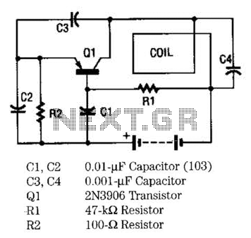
The metal locator utilizes a one-transistor oscillator in conjunction with an AM radio to detect metal. Transistor Q1 is a PNP transistor connected to the oscillator circuit. Resistor R1 supplies the appropriate base bias, while capacitors C3 and C4,...
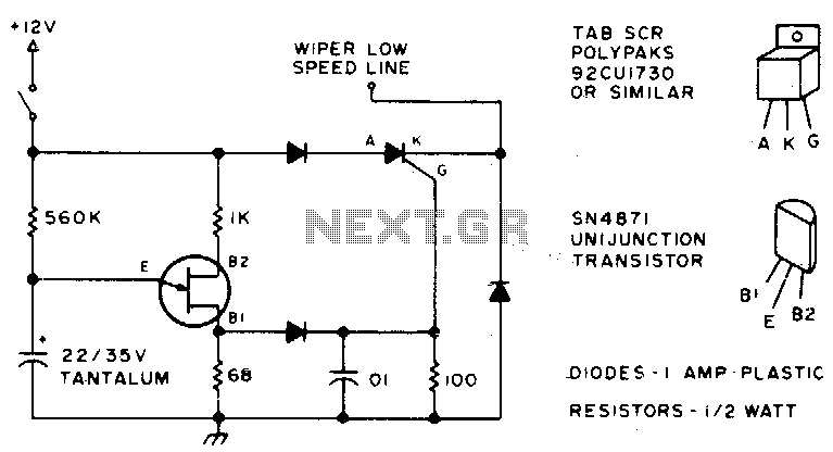
Here is an effective method to configure windshield wipers using an interval circuit. This setup requires only two connections to the car's wiper control, in addition to a ground connection. Variable control can be achieved by replacing a 560...
This is a remote on-off switch circuit. This circuit allows the use of a small switch to control larger AC currents from high-power devices. The remote on-off switch circuit operates by utilizing a low-power control signal to manage a high-power...
Gates U1-a and U1-b of the 4093 quad 2-input NAND Schmitt trigger are connected in variable, low-frequency square-wave oscillator circuits. The output of gate U1-a is connected to one of the inputs of gate U1-b. The square-wave output of...
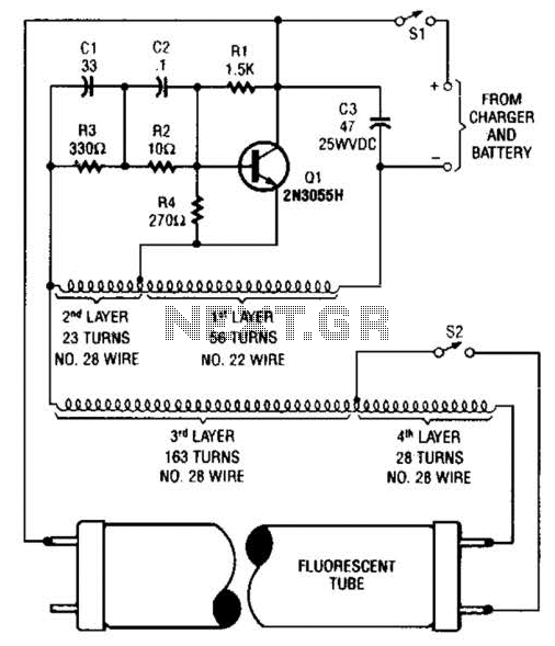
A 2N3055 oscillator (Q1) drives a homemade transformer, wound on a Vk ferrite rod. S2 is used as a filament switch and can be eliminated if desired. A 20-W fluorescent tube is recommended. The supply voltage is 12 V. The...
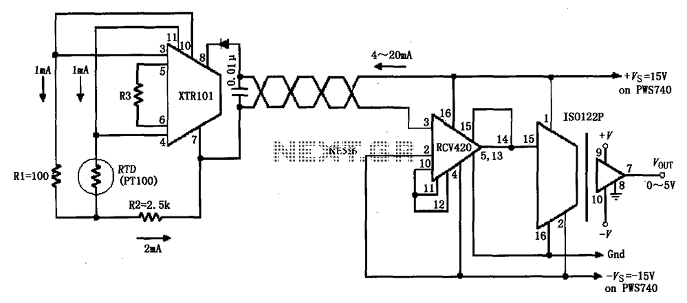
The circuit comprises an isolated RTD loop current configuration utilizing the XTR101 for transmitting loop current and the RCV420 for receiving it. The instrumentation amplifier detects changes in temperature via a resistance temperature detector (RTD), converting these changes into...