
Temperature Controlled Relays 4001/4011

The circuit described consists of two separate temperature control systems that utilize a relay for switching based on temperature thresholds. Each circuit is designed to monitor temperature variations and activate a relay accordingly, either to turn on or off a connected load based on the temperature readings.
In the first circuit, the relay is activated when the temperature exceeds a predefined upper limit. This is achieved through a thermistor, which changes its resistance with temperature variations. The output voltage at pins 5 and 6 of the circuit is critical for determining the activation of the transistor, which in turn controls the relay. The transistor's role is to amplify the signal from the thermistor, allowing the relay to be energized when the temperature surpasses the set point.
Conversely, the second circuit is designed to energize the relay when the temperature drops below a specified lower limit. This circuit is nearly identical to the first, with the primary distinction being the reversed polarity of the transistor. This configuration ensures that the relay is activated when the temperature falls below the desired threshold.
The thermistor's resistance value is not critical to the overall function of the circuit; however, the voltage across pins 5 and 6 must be monitored to ensure proper operation. Adjustments may be necessary for resistor R1 to calibrate the temperature range for activation, allowing for customization based on specific application requirements.
It is imperative to note that the on-board relay should not be utilized for switching mains voltage due to inadequate isolation between the relay contacts and the low-voltage components. For applications requiring the switching of mains voltage, it is recommended to use a suitably rated relay installed in a safe, isolated location to prevent any potential hazards. This precaution ensures the safety of both the circuit and the user, minimizing the risk of electrical shock or damage to components.The first circuit energizes the relay when the temperature rises above the preset level. The second circuit energizes the relay when the temperature falls below the preset level. The two circuits are practically identical. The only difference between them is the polarity of the transistor. The value of the thermistor is not critical. The important thing is the voltage on pins 5 & 6. Any value thermistor should work satisfactorily. But you may need to change the value of R1 - to achieve the desired range of adjustment. Do not use the "on-board" relay to switch mains voltage. The board's layout does not offer sufficient isolation between the relay contacts and the low-voltage components. If you want to switch mains voltage - mount a suitably rated relay somewhere safe - 🔗 External reference
Related Circuits
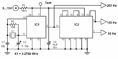
This circuit generates a 50 Hz timebase signal that is independent of the power line frequency. It is designed to provide the 50 Hz signal for electronic circuits that operate specifically with this clock frequency, primarily for circuits and...
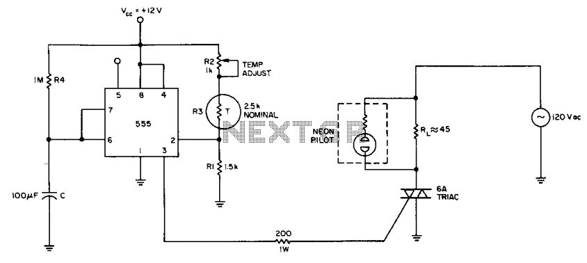
The internal comparator of the 555 timer, combined with a thermistor, creates a low-cost temperature controller. Resistor R2 establishes the temperature trip point. The 555 timer is a versatile integrated circuit widely used in various applications, including timers, oscillators, and...
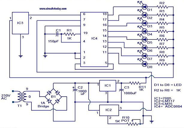
A digital temperature sensor circuit is explained with a circuit diagram. ICs ADC 0804, LM35, and LM317 are used in this digital circuit project. The digital temperature sensor circuit utilizes three primary integrated circuits (ICs): the ADC 0804, LM35, and...

This 555 timer circuit temperature monitoring system project can monitor temperature at up to four points. The system allows for the selection of whether the alarm should be triggered when the temperature increases or decreases, depending on the resistance...
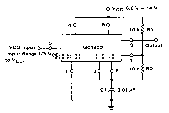
The VCO circuit, which has a nonlinear transfer characteristic, will operate satisfactorily up to 200 kHz. The VCO input range is effective from V% Vcc to Vcc - 2 V, with the highest control voltage producing the lowest output...
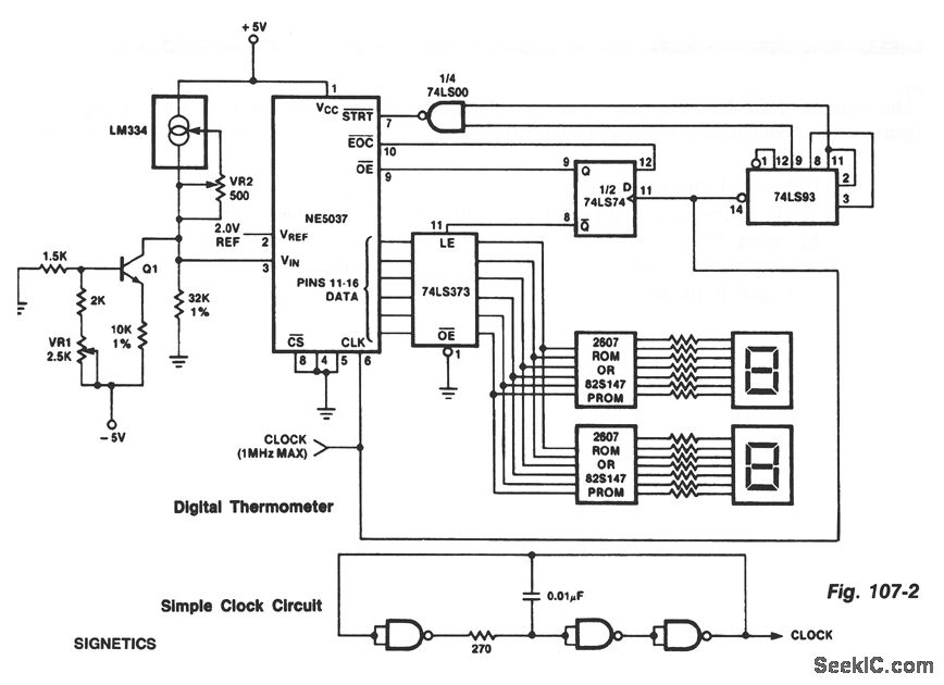
The ROMs or PROMs must contain the correct code for converting data from the NE5037, which serves as the address for the ROMs or PROMs, into the appropriate segment driver codes. The displayed temperature can be converted to degrees...