
Digital Temperature Sensor Circuit using ADC0804 LM35 and LM317

The digital temperature sensor circuit utilizes three primary integrated circuits (ICs): the ADC 0804, LM35, and LM317. The LM35 is a precision temperature sensor that outputs an analog voltage proportional to the temperature in degrees Celsius. This output is typically in the range of 0 to 1V for temperatures from 0°C to 100°C, making it suitable for various temperature monitoring applications.
The ADC 0804 is an 8-bit analog-to-digital converter that converts the analog voltage output from the LM35 into a digital signal. This conversion is essential for interfacing with microcontrollers or digital processing systems, allowing for digital display or further processing of temperature data. The ADC 0804 operates with a reference voltage, which must be carefully selected to ensure accurate conversion across the desired temperature range.
The LM317 is a voltage regulator that can be used in this circuit to provide a stable voltage supply to the LM35 and ADC 0804. It can adjust the output voltage based on the resistors used in its configuration, ensuring that the sensor and converter operate within their specified voltage ranges.
The circuit diagram typically includes connections between the LM35, ADC 0804, and LM317, along with additional components such as resistors and capacitors for signal conditioning and stability. Proper layout and grounding techniques should be employed to minimize noise and ensure accurate readings.
This digital temperature sensor circuit is versatile and can be adapted for various applications, including environmental monitoring, HVAC systems, and industrial automation, where precise temperature measurement is critical.A digital temperature sensor circuit is explained with circuit diagram.ICs ADC 0804,LM35 and LM317 are used in this digital circuit project.. 🔗 External reference
Related Circuits
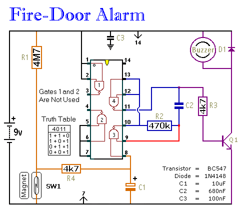
This circuit provides an alert when a door that should remain closed is left open. It is designed to be attached to a fire door, allowing normal passage. If the door remains open for more than 30 seconds, a...

The modification of the differential circuit is illustrated. In Figure A1, an integrator is depicted, and the output is presented. The circuit modification involves integrating the differential circuit with an integrator component, which plays a crucial role in signal processing...

This circuit utilizes invisible infrared light to detect the movement of individuals passing through a doorway. A short beep is produced when the infrared beam is interrupted. The circuit operates by employing an infrared transmitter and a receiver. The transmitter...
This triac-based 220V AC motor speed controller circuit is designed for controlling the speed of small household motors, such as drill machines. The motor speed can be adjusted by altering the setting of P1, which determines the phase of...

This is a simple touch switch circuit where the 555 timer is configured as a one-shot multivibrator triggered by touching the touch terminal. In monostable mode, the timer generates a fixed pulse of approximately 4 seconds whenever the trigger...

The schematic illustrates the subwoofer amplifier stage, specifically the pre-amplifier circuit and the signal processing circuit. Notably, it features two LM3886 power ICs from the American company NS, which facilitate BTL (Bridge-Tied Load) speaker operation at an 8-ohm impedance...