
Automobile Interior Lights Fader

The automobile interior lights fader circuit is an essential enhancement for older vehicles, providing a more modern aesthetic and functionality to the interior lighting system. The circuit operates by controlling the voltage applied to the interior lights, allowing for a smooth transition between bright and dim states.
The LM324 operational amplifier serves as the primary element, configured in a way that enables it to function as a variable resistor. This configuration allows for the gradual increase and decrease of current flowing to the lights, resulting in a fading effect.
The circuit typically includes additional components such as resistors, capacitors, and possibly a potentiometer, which can be adjusted to set the rate of fading. The resistors determine the current flow, while the capacitors are responsible for creating a time delay, thus controlling the fading speed.
To implement this circuit, it is essential to ensure proper power supply connections and to select components that can handle the voltage and current requirements of the vehicle's interior lighting. The circuit can be installed in conjunction with the vehicle's existing lighting system, allowing for seamless integration without significant modifications.
In summary, this fader circuit not only adds a sophisticated touch to the vehicle's interior lighting but also enhances user experience by providing a gradual transition in light intensity, making it a valuable upgrade for older automotive models.Automobile Interior Lights Fader Circuit diagram Circuit This circuit is similar to the fading eyes circuit above and is used to slowly brighten and fade interior lights of older cars. The circuit is based around the LM324 low p.. 🔗 External reference
Related Circuits

The circuit is simple and straightforward. Two inputs are included to demonstrate input control and software debouncing. An ATMEL microcontroller AT89C2051 is utilized to control the sequential glowing of LEDs, creating a running light effect. A 12 MHz crystal...
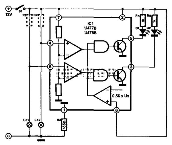
This circuit is designed for monitoring automotive lighting. Two specialized integrated circuits (ICs) from Telefunken are used to measure the current through a light bulb. Detecting whether current flows through a bulb is an effective method to determine its...
Most cars do not have delayed interior lights. The circuit presented can rectify this issue by gradually switching the interior lights of a car on and off. This feature facilitates tasks such as locating the ignition keyhole after the...
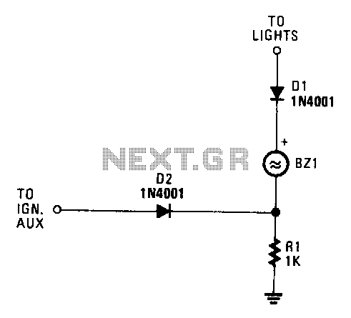
When both the ignition and the car lights are activated, piezo transducer BZ1 does not draw any current and remains silent. If only the ignition is on, diode D1 is reverse-biased, which prevents current from flowing through BZ1. However,...
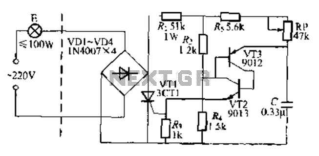
The circuit is a one-way ordinary transistor-triggered dimmer light circuit. It uses a complementary amplifier configuration with transistors VT2 and VT3 to form the thyristor trigger circuit for VT1. The circuit operates with a 220V alternating current through the...
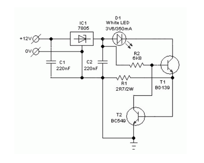
A simple and safe white LED driver circuit has been designed for use in 12V automobiles, allowing for the efficient operation of standard high-efficiency white LED modules powered by automotive battery systems. The circuit utilizes a fixed voltage regulator...