
Run Lights

The circuit design focuses on a sequential LED driver system using the ATMEL AT89C2051 microcontroller. This microcontroller operates at a frequency of 12 MHz, determined by the attached crystal oscillator, which ensures accurate timing for LED activation. The circuit features two input lines that serve dual purposes: they allow for user interaction and facilitate software debouncing, which is crucial for preventing erroneous multiple triggers from mechanical switches.
The microcontroller's VCC pin is connected to a 5V power supply, with a 0.1 µF capacitor connected to ground. This capacitor acts as a bypass capacitor, filtering out high-frequency noise and stabilizing the power supply voltage, thereby enhancing the performance of the microcontroller and reducing the risk of interference from external radio frequency sources.
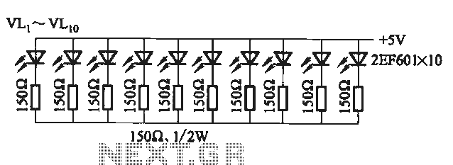
The LED control logic is implemented in the microcontroller's firmware, which sequentially activates the LEDs connected to its output pins. Each LED is turned on and off in a programmed sequence, creating a visually appealing running light effect. The circuit can be expanded or modified by adding more LEDs or adjusting the timing parameters in the firmware to create different light patterns.
Additional features may include the integration of resistors in series with the LEDs to limit current and prevent damage, as well as the potential for additional input mechanisms, such as push buttons or sensors, to alter the LED sequence dynamically. Overall, this circuit exemplifies a practical application of microcontroller technology in creating visually engaging light displays.Circuit is very simple and straightforward. Two inputs are added just to give an idea of input control and software denouncing. An ATMEL Micro-controller AT89C2051 is used to control the LED glowing one by one to give the effect of running light. A 12 M Hz crystal is used for basic timings of controller. Micro-controller VCC pin has grounded by on e 0. 1 uF capacitor, it should always to be grounded very near to micro-controller VCC pin to protect by and RFI (Radio Frequency interference). 🔗 External reference
Related Circuits

The circuit comprises three main components. The first component features an oscillator, while the second component includes a mod 16 counter (7493). The oscillator is configured in self-triggered mode, and a potentiometer (VR1) is utilized for speed control of...

The circuit employs two Light Dependent Resistors (LDRs) arranged in series with a separation of approximately half a meter. This configuration allows each LDR to detect the presence of a person entering or exiting the room. The processed outputs...
The circuit utilizes a 555 timer configured as a multivibrator, where the oscillation frequency is determined by resistors R1, R2, and capacitor C1. The frequency formula is given by fo = 1.443 / ((R1 + R2) * C1). The...

This toy traffic signal utilizes a single low-cost hex Schmitt-trigger inverter IC (IC1a-IC1f) to directly control three colored LEDs (red, green, and amber). Upon activation, the circuit illuminates the red signal for 30 seconds, followed by green for 6...

The circuit consists of two building blocks. The first is a square wave oscillator made up of two transistors in a multivibrator arrangement and the second is a CD 4017 decade counter IC. The multivibrator contains two extra components...
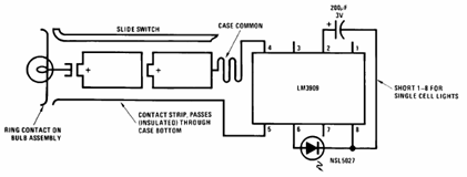
The schematic presented below illustrates the Flashlight Finder circuit diagram utilizing the LM3909, a monolithic oscillator specifically designed for flashing Light Emitting Diodes (LEDs). The Flashlight Finder circuit employs the LM3909 integrated circuit, which is capable of generating a series...