
Automotive electronic password lock circuit diagram

The automotive electronic code lock circuit utilizes an integrated circuit (IC) 5G058, which serves as the core controller for the locking mechanism. The circuit is designed to enhance vehicle security by requiring a specific sequence of key presses to unlock the system. The six valid input keys, labeled S1 through S6, must be pressed in the correct order to successfully disengage the lock. This sequential requirement helps to prevent unauthorized access, as random key presses will not unlock the system.
The external key switch connects to the power supply, providing the necessary voltage for the circuit to operate. Each key input is monitored by the IC, which processes the sequence and determines whether the input is valid. If the correct sequence is followed, the IC will activate the unlocking mechanism, allowing access to the vehicle.
In addition, the circuit includes a button switch, denoted as S7, which is connected to a false key input. This feature serves as a deterrent against tampering. If an incorrect key is pressed, the circuit can trigger an alarm or other security measures, alerting the owner to potential unauthorized attempts to access the vehicle.
Overall, the automotive electronic code lock circuit is a sophisticated security solution that combines ease of use with robust protection against theft. The design emphasizes reliability and user-friendliness, making it an effective choice for modern automotive applications.Automotive electronic code lock circuit is shown as above. ICl is exclusive lock for the integrated circuit 5G058, its ? ~ ? feet connect external key switch to the power supply. They are six valid input keys. The unlock must follow the sequence of Sl ~ S6; pin ? button switch S7 is connected to the false key input. It is free to pick one or a few keys on.. 🔗 External reference
Related Circuits
The SL517 is designed as an audio, RF, or infrared decoder circuit suitable for electronic toy applications. The internal circuitry consists of an analog amplifier, a frequency divider, a bistable circuit, and a driver. It utilizes CMOS technology, has...
The following circuit illustrates a Single Supply Phase Locked Loop Circuit Diagram. This circuit is based on the LM331 integrated circuit. Features include the response of... The Single Supply Phase Locked Loop (PLL) circuit utilizing the LM331 integrated circuit is...
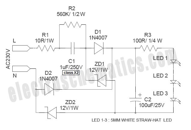
White Light Emitting Diodes (LEDs) now available can serve as a strong alternative to incandescent lamps in lighting applications. Today's White LEDs are... White Light Emitting Diodes (LEDs) represent a significant advancement in lighting technology, offering energy efficiency, longevity, and...
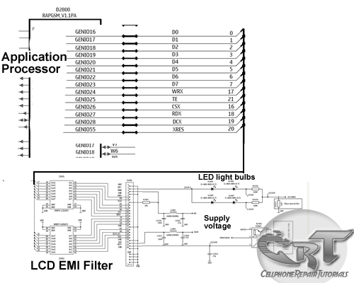
An LCD (liquid crystal display) is an electronically modulated optical device composed of multiple pixels filled with liquid crystals, arranged in front of a light source (backlight) or reflector to create images in color or monochrome. The block diagram...
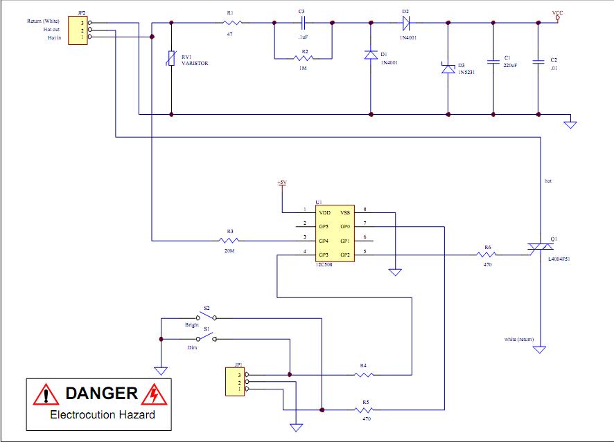
Assistance is required to modify a light dimmer circuit connected to a PIC12C508 microcontroller. This circuit is designed for the... The light dimmer circuit utilizing the PIC12C508 microcontroller serves to control the brightness of a light source through pulse width...
Transistors Q1 and Q2, along with resistors R1 through R7, form the input balancing stage that measures the resistance between points X and Y. This stage operates as a bridge circuit, incorporating resistors R1, R2, R6, R7, and the...