
Simple Short Finder Circuit

The circuit employs a differential input configuration using transistors Q1 and Q2 to achieve precise balancing and measurement of the resistance between points X and Y. This configuration ensures that any changes in resistance can be accurately detected, allowing the circuit to function effectively as a short circuit tester. The bridge circuit is carefully designed with resistors R1, R2, R6, and R7 to provide a stable reference for the input stage.
Transistors Q3 and Q4 serve as the switching elements for the buzzer, which is a critical component in providing audible feedback to the user. The operation of Q2 is central to the circuit's functionality; when the input resistance is high, Q2 remains in an active state, maintaining a low output, which prevents the buzzer from sounding. This condition indicates that there is no short circuit present. However, once the resistance falls below the defined threshold, Q2 switches off, leading to a high output that activates the buzzer, alerting the user to the presence of a short circuit.
The adjustable frequency of the buzzer, set at approximately 1000 Hz, can be fine-tuned by altering the capacitance of capacitor C, providing flexibility in the circuit's auditory feedback. This feature can be particularly useful in applications where different sounds may be required to indicate various conditions or thresholds. Overall, this circuit design effectively combines analog components to create a reliable short circuit detection system with user-friendly feedback mechanisms. Transistors Ql and Q2, together with resistors Rl through R7, make up the input balancing stage, which senses the resistance between points X and Y. The input stage is essentially a bridge, consisting of Rl, R2, R6, R7, and the resistance between points X and Y.
Transistors Q3 and Q4 and their associated passive components form a buzzer, which sounds when the tester detects a short. The buzzer is controlled by the output from Q2. When the input resistance is high (more than about 10 ), Q2 turns on, so its collector potential is close to ground, and the buzzer remains off.
When the input resistance is sufficiently low, Q2 turns off, and the buzzer sounds. The frequency of the sound, which is about 1000 Hz, can be adjusted by varying the value of capacitor (C).
Related Circuits
With a 1.5V battery supply, the integrated circuit LM3909 can drive the light-emitting diode NSL5027. The 300μF electrolytic capacitor acts as a timing capacitor, which limits the flash speed to approximately 1Hz. The circuit utilizes the LM3909, a popular LED...
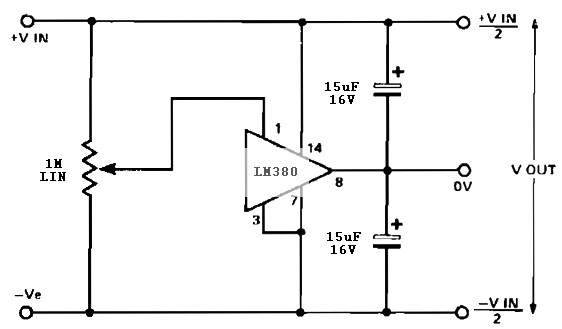
A simple split rail power supply based on the LM380 power supply. The design is intended to provide an inexpensive high-power supply, initially available in three power levels. A wide range of accessories is included to maintain an attractive...
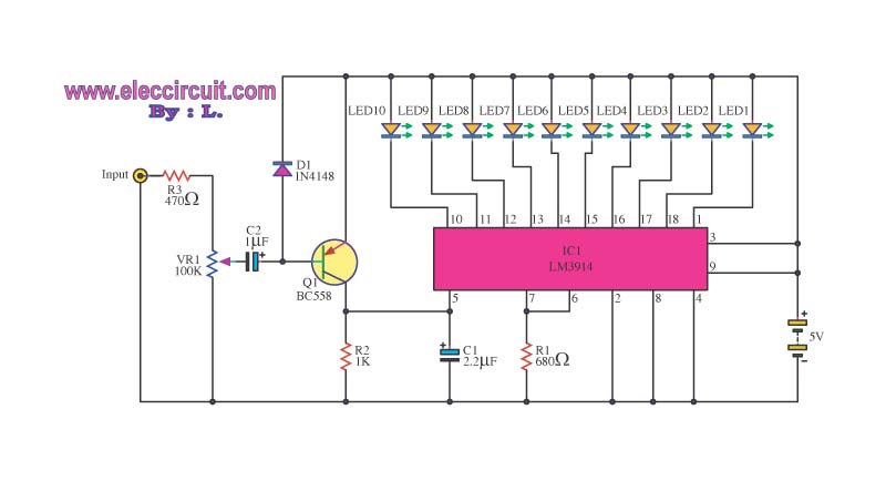
This is a simple light-running circuit synchronized with music. The circuit is straightforward, operating in mono, and requires only a few components. It can be connected to the output of a CD player. The described circuit utilizes a basic audio...
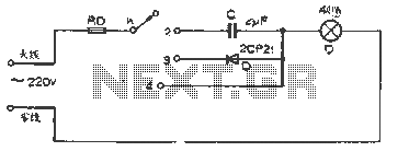
The figure illustrates a basic dimming lights circuit. The light intensity is controlled by a multi-speed control switch, designated as K. When switch K is set to position "1," the lights are turned off. In position "2," the light...
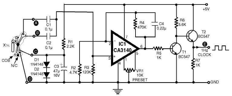
1Hz Clock Generator Circuit with Chip On Board (COB). The COBs used in different watches may differ somewhat in their configuration. However, through trial and error, one can identify the appropriate points corresponding to points A, B, C, and...
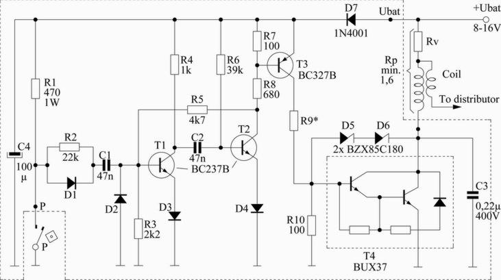
This scheme is designed for a four-cylinder engine. It aims to reduce fuel consumption, increase speed slightly, and minimize the need for frequent access to the distributor cap for contact button replacement, thereby saving costs. Transistors T1 and T2...