
AVR Dongle

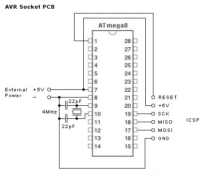
The circuit utilizes a parallel port interface to facilitate communication with the AVR microcontroller, specifically designed for programming tasks. The inclusion of IC1 as a buffer is crucial, as it ensures that the signals from the parallel port are adequately conditioned for the microcontroller's input requirements, thus preventing potential damage from signal levels that are too high or too low. The use of standard ISP pinouts (K2 and K3) aligns with industry practices, allowing for compatibility with a wide range of AVR development boards and tools. This design choice not only enhances usability but also promotes a modular approach to microcontroller programming.
The programming software, ATMEL AVR ISP, is essential for executing the programming sequence. It communicates with the microcontroller through the buffered signals, allowing for the transfer of firmware or configuration data. Users are encouraged to download this software to facilitate the programming process effectively.
For construction, the circuit is intended to be assembled on a standard prototype board. This approach allows for flexibility in layout and component placement, accommodating various configurations. The simplicity of the design, characterized by a minimal number of components, aids in reducing assembly errors. It is recommended that builders, particularly those with limited experience, follow a systematic approach by marking off connections on the schematic as they are completed. This method not only aids in ensuring accuracy but also serves as a valuable learning tool for understanding circuit assembly and troubleshooting. Overall, this circuit serves as an accessible introduction to programming AVR controllers, making it suitable for both novice and experienced users.This circuit is intended to program AVR controllers such as the AT90S1200 via the parallel port. The circuit is extremely simple. IC1 provides buffering for the signals that travel from the parallel port to the microcontroller and vice versa. This is essentially everything that can be said about the circuit. The two boxheaders (K2 and K3) have the standard` ISP (in system programming) pinout for the AVR controllers. The manufacturer recommends these two pinouts in an attempt to create a kind of standard for the in-circuit programming of AVR-controllers. These connections can be found on many development boards for these controllers. The software carries out the actual programming task. It is therefore necessary to have a program (ATMEL AVR ISP), which is available as a free download from The construction of the circuit will have to made on standard prototype board, since we didn`t design a PCB for this circuit.
This should not present any difficulties considering the small number of parts involved. We recommend that inexperienced buildersrst make a copy of the circuit and cross off each connection on the schematic once it has been made on the board. This makes it easy to check after-wards whether all connections have been made or not. 🔗 External reference
Related Circuits
To program an AVR microcontroller using a USB port instead of parallel or serial interfaces, USBasp is the most suitable option. A circuit diagram for USBasp is available. The procedure for burning the hex file includes installing avrdude (WinAVR),...
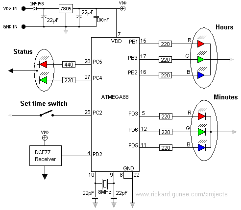
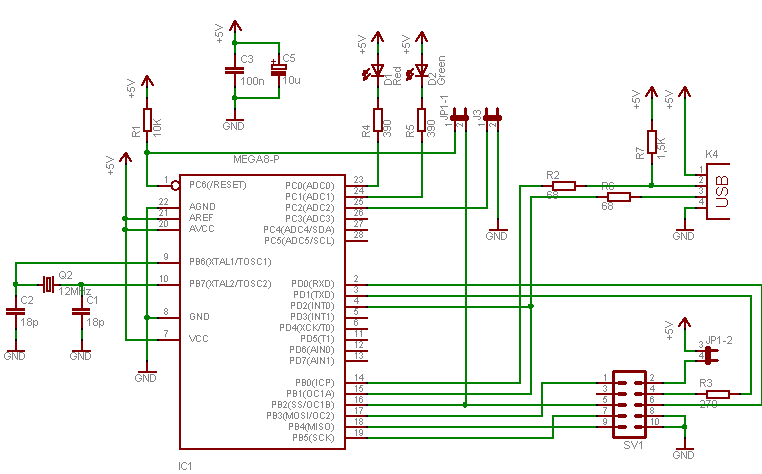
This page describes a color clock that displays the time using two RGB LEDs, one for hours and one for minutes. It uses standard color coding for components, with two additional colors to accommodate the twelve distinct color representations...
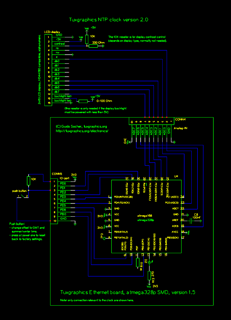
The Network Time Protocol (NTP) has transformed global timekeeping, enabling accurate date and time retrieval from anywhere in the world. NTP is a straightforward UDP-based protocol that can be implemented in microcontrollers. The Tuxgraphics NTP clock has gained popularity...
This simple AVR programmer is capable of transferring hex programs to most Atmel AVR microcontrollers. It is more reliable than many other basic AVR programmers available and can be assembled in a short amount of time. This programmer supports...

The module provides a pre-wired multiplex of a 4-digit common anode LED, which is quite useful. The soldering pad for these signals is shown in the first picture below. A friend provided an AT90S2313 chip, along with a simple...
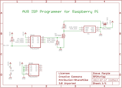
As a fully-featured Linux computer, many external programmers can be used with the Raspberry Pi to program the Atmel AVR range of microprocessors. It is also possible to utilize the general-purpose input/output lines (GPIOs) found on the Raspberry Pi...