
Simple Serial AVR Programmer

This AVR programmer design emphasizes simplicity and reliability, making it an excellent choice for both hobbyists and professionals working with AVR microcontrollers. The ability to program multiple microcontroller types expands its utility across various projects. The integration of the programming cable directly into the circuit board allows for seamless programming without the need for chip removal, which is particularly advantageous in applications where the microcontroller is embedded within a larger system.
The PCB layout for this programmer should include a standard 6-pin or 10-pin ISP header, which is commonly used for AVR programming. This header facilitates the connection between the programmer and the target microcontroller. The programmer circuit typically consists of a few essential components, including the microcontroller interface, a voltage regulator to ensure stable power supply, and the crystal oscillator for timing.
For the programming process, the software interface, such as PonyProg, communicates with the programmer via a serial or USB connection, sending the hex file data to the microcontroller. The programming sequence involves erasing the chip, writing the new firmware, and verifying the written data to ensure integrity.
When designing the programmer, attention must be paid to the power supply requirements of the target microcontroller, as well as the logic levels used in the programming signals. This ensures compatibility with a wide range of AVR devices. Additionally, implementing protection features, such as a reset button and LED indicators for power and programming status, can enhance user experience and safety during operation.
Overall, this AVR programmer is a versatile and efficient tool for programming a variety of Atmel AVR microcontrollers, making it an essential component for any electronics engineer or enthusiast working with embedded systems.This simple AVR Programmer able to transfer hex programs to most ATMEL AVR microcontrollers. It is more reliable than most other simple AVR programmers available out there and can be built in very short amount of time. This Programmer support the AVR microcontroller ATmega103, ATmega161, ATmega163, ATmega 323, ATmega128, ATmega8, ATmega16, ATmega6
4, ATmega32, ATmega162, ATmega169, ATmega8515, ATmega8535, ATmega44, ATmega88, ATmega168, ATmega164, ATmega324, ATmega644, ATmega640, ATmega1280, ATmega1281, ATmega2560, ATmega2561, AT90can32, AT90can64, AT90can128, ATtiny12, ATtiny15, ATtiny26, ATtiny2313, ATtiny13, ATtiny25, ATtiny45, ATtiny85, ATtiny261, ATtiny461, and ATtiny861. you can also use it directly in the main circuit by adding a pin to plug this cable programmers, so you do not need to remove the chip while it is to program.
The PCB connector has been created to match the ATmega8 AVR microcontroller, 28-DIP, but you can build a PCB socket for each other AVR microcontroller out there. This AVR programmer software is compatible with popular PonyProg showing the status bar the progress of programming.
This minimum system schematics using crystal 4 Mhz, you can use other crystal frequency depend on your fuse bit setting, please be careful when setting fuse bit and security lock. if you wrong. you can`t recovery your chips and your chips will damage. expected, you have High voltage programmer. 🔗 External reference
Related Circuits
The receiver circuit in Figure 1 activates an audio alarm when the transmitter (Figure 2) moves beyond a specified perimeter. The transmitter functions as a voltage-controlled oscillator, operating at approximately 915 MHz within the unlicensed ISM (industrial/scientific/medical) band. It...
A potentiometer regulates the firing point of the triac. Capacitor C4 is charged through resistors R3, R4, P1, and R5. After a specific duration, determined by the potentiometer setting, the charge in C4 becomes sufficient for the diac D...
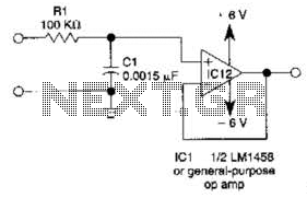
This simple filter utilizes an RC section as the filter element, incorporating a voltage follower to manage other frequencies. The -3 dB point is calculated as 1/(6.28 * RXCV), resulting in a response that drops 6 dB per octave...

One of the simplest methods of metal detection is through a beat frequency oscillator. The circuit consists of two balanced oscillators: one provides a reference signal, while the other acts as the detector element. The frequency of the reference...
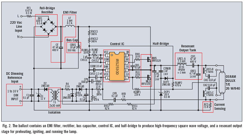
Fluorescent dimming systems can enhance visual comfort and lower utility costs through strategies such as daylight harvesting, demand reduction, and scheduled dimming. A dimming electronic ballast plays a crucial role in this system. To execute dimming functions, the ballast...
The two circuits below illustrate using the 555 timer to close a relay for a predetermined amount of time by pressing a momentary N/O push button. The circuit on the left can be used for long time periods where...