
AVR Dongle

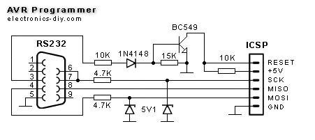
The circuit operates by interfacing the parallel port of a computer with the AVR microcontroller. The parallel port, often referred to as a printer port, consists of multiple data lines that can be utilized to send programming instructions to the microcontroller. The simplicity of the design allows for easy implementation and troubleshooting.
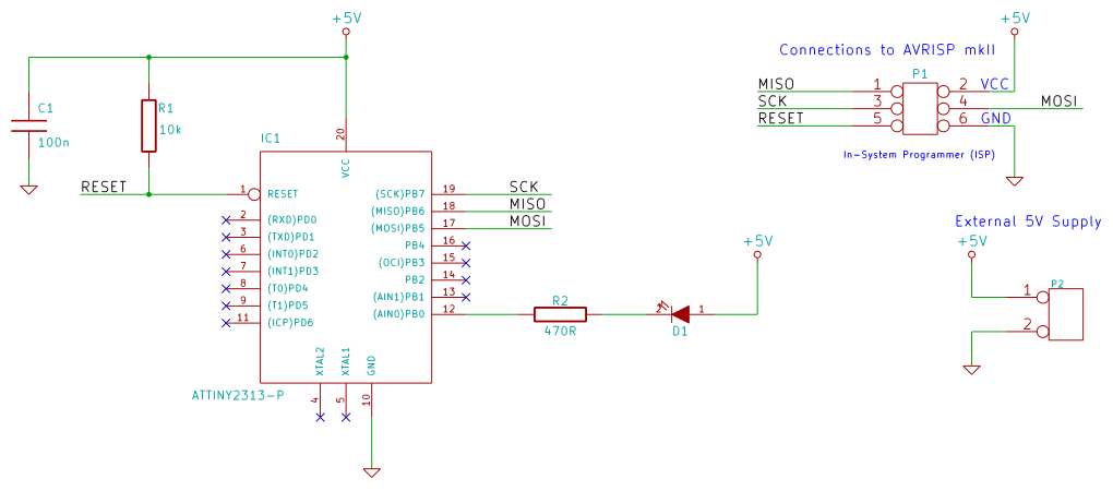
IC1, which functions as a buffer, is critical in ensuring that the signals from the parallel port are properly conditioned for the microcontroller. This component protects the microcontroller from potential damage due to voltage levels or current that may exceed its input specifications. The buffer also helps to isolate the parallel port from the microcontroller, enhancing the reliability of the programming process.
The circuit typically includes several additional passive components, such as resistors and capacitors, to stabilize the power supply and filter any noise that may affect the programming signals. A power supply circuit may also be included to provide the necessary voltage levels for the AVR microcontroller during programming.
Connections between the parallel port and the microcontroller are made through a series of pins, with specific lines designated for data transmission and control signals. The programming process involves sending a sequence of binary data that corresponds to the firmware being uploaded to the microcontroller's memory.
Overall, this circuit represents a practical solution for programming AVR controllers in a cost-effective manner, utilizing readily available components and straightforward design principles.This circuit is intended to program AVR controllers such as the AT90S1200 via the parallel port. The circuit is extremely simple. IC1 provides buffering f.. 🔗 External reference
Related Circuits
A microcontroller operates using digital language, while the inputs it receives from the environment are predominantly analog, meaning they change continuously over time. To enable the microcontroller to interpret these inputs, an Analog to Digital Converter (ADC) is utilized....
The module provides a pre-wired multiplex of a 4-digit common anode LED, which is quite useful. The soldering pad for these signals is shown in the first picture below. A friend provided an AT90S2313 chip, along with a simple...
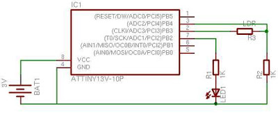
When first encountering this article, it is apparent that it presents an excellent project utilizing only a few components. Microcontroller projects based on LEDs are particularly appealing. This project involves the design and implementation of a microcontroller-based LED circuit, which...
This simple AVR Programmer allows the transfer of hex programs to most Atmel AVR microcontrollers without compromising budget and time. It is more reliable than many other basic AVR programmers available and can be assembled in a short timeframe....
This tutorial examines the essential tools required for developing C programs on 8-bit AVR microcontrollers. It demonstrates how to write a C program and upload it to an AVR microcontroller, specifically utilizing an ATtiny2313 microcontroller breadboard circuit as a...

The AVR 8-Bit RISC microcontroller from Atmel is a widely used microcontroller. This microcontroller integrates EEPROM, RAM, an Analog to Digital converter, numerous digital input and output lines, timers, UART for RS-232 communication, and various other features. An article...