
AVR Inductance / Capacitance meter

To convert from frequency to inductance or capacitance requires a pocket calculator or spreadsheet, and is fine if only taking a few measurements per day. Beyond that, the manual labor seems a bit much, and the time to complete a measurement and calculation becomes burdensome. As I found myself spending more time winding transformers in my Thailand lab for various power supplies that I longed for a meter that would read out directly in inductance and capacitance, such as I had in my lab in Arizona. An LC oscillator oscillates at the resonant frequency of a parallel LC resonant circuit. When measuring an inductor, a precision capacitor is switched in to the circuit. When measuring a capacitor, a precision inductor is switched into the circuit.
If the Q of the resonant circuit is about 10 or greater, the measurement error contributed by this factor will be less than 1%. Q is the comparison of the losses in the circuit, often the result of resistance in the circuit, with the reactance of the inductor and capacitor. The Q of good quality capacitors is usually not a problem - just keep away from ceramic and electrolytic capacitors and you shouldn't have a problem. The Q of the inductor is the one to watch out for. The first inductor that I used had a Q of 3 when measuring a 0.47 uf capacitor, and that made the error nearly 20%!
Q of the inductor is of greatest concern at the lowest operating frequency. In this application, this corresponds to the situation in which the highest value capacitor is being measured. A 1 mH inductor resonates with a 1 uf capacitor at 5.035 kHz. The reactance of the inductor is 6.28 x 5.035 kHz x 1mH = 31.6 Ohms. In order to keep the error contributed by the Q of the coil to less than 1% of the measured value, the Q must be 10, so the resistance of the resonant circuit must be less than 1/10 of the reactance, or 3.16 Ohms. You can check the resistance of inductors you are considering for use as L2 with an Ohmmeter to find its resistance.
Before measuring, the circuit's offset reactance needs to be measured and removed, using a zero set procedure. Turn the meter on for a few seconds, to allow enough time for the analog circuitry and the readings to settle, then if measuring an inductor, short the Lx/Cx terminals together, or if measuring a capacitor, leave the terminals open. Press the ZERO SET button and hold it down for a couple of measurement cycles. The LED blinks one time each measurement cycle. Release the ZERO SET button, and after the current measurement cycle is completed, the meter should read zero.
The only difficulty in getting the instrument to display inductance and capacitance directly was in organizing the assembly language code, and probably more importantly, properly scaling the operations. I had looked into it, and it seems to be too much trouble. It would take about as much time and energy to add this feature to the LC meter as it would to learn to use a C compiler. So, that's why this project is written in C.
The described instrument functions as an LC meter capable of measuring inductance (L) and capacitance (C) with high precision. The core principle relies on an LC oscillator that resonates at the frequency determined by the inductor and capacitor in the circuit. For operation, the user begins with either a precision capacitor or a precision inductor, while the meter allows for the selection or adjustment of the other component. This feature simplifies the measurement process, eliminating the need for range switching or relays, thus enhancing user experience and accuracy.
The measurement technique involves the calculation of inductance and capacitance based on the oscillation frequency, which is derived from the resonant frequency of the LC circuit. The Q factor, or quality factor, of the circuit plays a critical role in measurement accuracy. A Q factor of 10 or greater is ideal, as it minimizes measurement errors to less than 1%. Careful selection of components is essential, particularly the inductor, which should have a high Q to reduce losses that could affect the accuracy of readings.
A zero set procedure is integral to the operation of the meter to ensure accurate readings. This involves stabilizing the circuit before measurements are taken. The user must allow the meter to settle and then appropriately short or open the terminals based on whether an inductor or capacitor is being measured. This calibration step is crucial for eliminating offset reactance from the measurements.
The implementation of the measurement logic is achieved through programming, with the choice of C language facilitating effective scaling and operation. The design allows for direct readings of inductance and capacitance, streamlining the process for users who require frequent measurements, particularly in laboratory or field settings.
Overall, this LC meter represents a refined approach to measuring inductance and capacitance, providing users with a reliable and efficient tool that integrates precision components and straightforward operational procedures.This instrument requires two precision components: A precision capacitor and a precision inductor. You only need to start with one precision component, either the reference capacitor or the reference inductor, and using this meter, you can select or adjust the other precision component. Calculates and displays L and C from oscillation frequency using reference components. No relays, no range switching, a minimum of controls. And it is pretty accurate too! The basis of this project is several similar projects on the world wide web and some magazine articles before the world wide web was a common means of information interchange. Unfortunately, I am not able to determine the originator(s) of the concept, but I suspect that it is as old as radio.
Another project on my web site, LC Determination by Resonant Frequency Measurement, measures the resonant frequency of an L/C circuit, but the hardware stops at the frequency measurement. It does not proceed to calculate the unknown inductance or capacitance. To convert from frequency to inductance or capacitance requires a pocket calculator or spreadsheet, and is fine if only taking a few measurements per day.
Beyond that, the manual labor seems a bit much, and the time to complete a measurement and calculation becomes burdensome. As I found myself spending more time winding transformers in my Thailand lab for various power supplies that I longed for a meter that would read out directly in inductance and capacitance, such as I had in my lab in Arizona.
An LC oscillator oscillates at the resonant frequency of a parallel LC resonant circuit. When measuring an inductor, a precision capacitor is switched in to the circuit. When measuring a capacitor, a precision inductor is switched into the circuit. If the Q of the resonant circuit is about 10 or greater, the measurement error contributed by this factor will be less than 1%. Q is the comparison of the losses in the circuit, often the result of resistance in the circuit, with the reactance of the inductor and capacitor.
The Q of good quality capacitors is usually not a problem - just keep away from ceramic and electrolytic capacitors and you shouldn't have a problem. The Q of the inductor is the one to watch out for. The first inductor that I used had a Q of 3 when measuring a 0.47 uf capacitor, and that made the error nearly 20%!
Q of the inductor is of greatest concern at the lowest operating frequency. In this application, this corresponds to the situation in which the highest value capacitor is being measured. A 1 mH inductor resonates with a 1 uf capacitor at 5.035 kHz. The reactance of the inductor is 6.28 x 5.035 kHz x 1mH = 31.6 Ohms. In order to keep the error contributed by the Q of the coil to less than 1% of the measured value, the Q must be 10, so the resistance of the resonant circuit must be less than 1/10 of the reactance, or 3.16 Ohms.
You can check the resistance of inductors you are considering for use as L2 with an Ohmmeter to find its resistance. Before measuring, the circuit's offset reactance needs to be measured and removed, using a zero set procedure.
Turn the meter on for a few seconds, to allow enough time for the analog circuitry and the readings to settle, then if measuring an inductor, short the Lx/Cx terminals together, or if measuring a capacitor, leave the terminals open. Press the ZERO SET button and hold it down for a couple of measurement cycles. The LED blinks one time each measurement cycle. Release the ZERO SET button, and after the current measurement cycle is completed, the meter should read zero.
The only difficulty in getting the instrument to display inductance and capacitance directly was in organizing the assembly language code, and probably more importantly, properly scaling the operations. I had looked into it, and it seems to be too much trouble. It would take about as much time and energy to add this feature to the LC meter as it would to learn to use a C compiler.
So, that's why this project is written in C. 🔗 External reference
Related Circuits
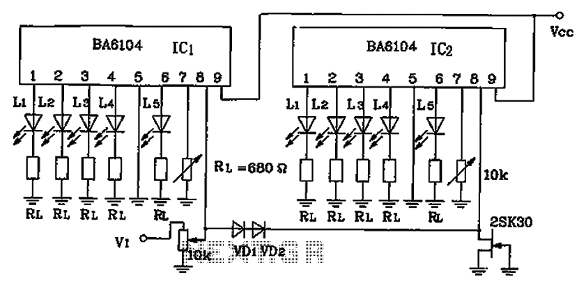
BA6104 is a five-digit LED level meter that functions as an LED display driver integrated circuit (IC). The configuration of the circuit is illustrated in the accompanying figure. The circuit utilizes a 10 by two-dot LED level display. The...
This document outlines a simple SWR meter designed for long and medium wave bands (137 kHz and 500 kHz). The design is not novel and resembles common short wave meters, but it has been specifically created to operate at...
One cannot expect high performance from a basic detector-based meter. Its sensitivity is merely sufficient to provide a fundamental understanding of the power output that the transmitter can achieve. The detector-based meter operates on a straightforward principle where it measures...
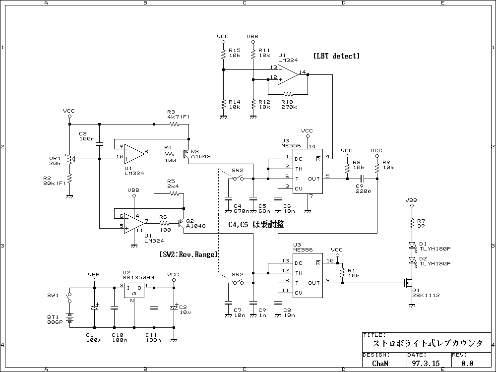
This is a simple rev-counter which can measure up to 100,000 rpm with method of strobe synchronization. Its usage is easy. Put a marker on the shaft before measuring, light on the shaft by flashing LED and adjust flashing...
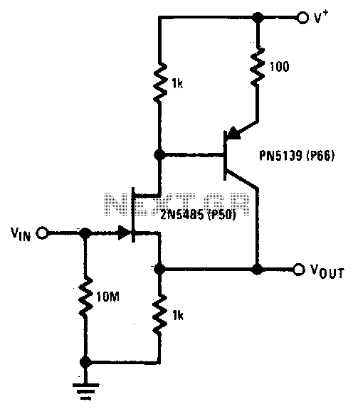
The 2N5485 features low input capacitance, making this compound series-feedback buffer a wide-band unity gain amplifier. The 2N5485 is a field-effect transistor (FET) that is often utilized in applications requiring low noise and high input impedance. Its low input capacitance...
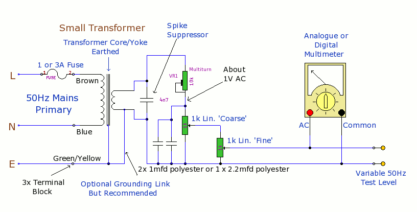
The purpose of this prototype unit is to eliminate the need for an oscillator. It provides a mains-derived and fully variable 50 Hz AC voltage, adjustable down to millivolts for comparison and accuracy testing of two or more parallel-connected...