
avr microcontroller project

The H-Bridge circuit is essential for controlling the direction and speed of DC motors, which are widely used in various applications such as robotics, automation, and automotive systems. The L293D IC, as a dual H-Bridge driver, simplifies the design by integrating multiple components into a single package, thus reducing the complexity of the circuit. This IC can control two motors independently, allowing for versatile configurations in applications requiring multiple motors.
The operating current specifications of the L293D indicate its capability to handle moderate loads, making it suitable for small to medium-sized DC motors. The inclusion of output diodes for back EMF protection is crucial, as it safeguards the circuit from voltage spikes that can occur when the motor is switched off or changes direction. This feature enhances the reliability and longevity of the motor driver circuit.
In the described application, the ATMEGA32 microcontroller plays a pivotal role in processing the signals received from the MPX4115 pressure sensor. The pressure sensor's capability to provide a high-level analog output, coupled with the microcontroller's ADC, allows for precise digital representation of pressure readings. The ADC module within the ATMEGA32 must be properly initialized to ensure accurate conversions from analog to digital signals, facilitating effective monitoring and control in the system.
This combination of components—the L293D motor driver, ATMEGA32 microcontroller, and MPX4115 pressure sensor—forms a robust platform for developing advanced control systems that require real-time feedback and motor actuation, making it suitable for applications ranging from industrial automation to consumer electronics.H-Bridge Circuit using transistors for bidirectional driving of DC motor. H-Bridges in IC`s to reduce the drive circuit complexity. L293D is a dual H-Bridge motor driver, So with one IC we can interface two DC motors which can be controlled in both clockwise and counter clockwise direction and if you have motor with fix direction of motion the you can make use of all the four I/Os to connect up to four DC motors. L293D has output current of 600mA and peak output current of 1. 2A per channel. Moreover for protection of circuit from back EMF ouput diodes are included within the IC. The output supply (VCC2) has a wide range from 4. 5V to 36V, which has made L293D a best choice for DC motor driver. As you can see in the circuit, three pins are needed for interfacing a DC motor (A, B, Enable). If you want the o/p to be enabled completely then you can connect Enable to VCC and only 2 pins needed from controller to make the motor work. Here, I try to explain is that a pressure sensor detects the pressure and passes an accordingly scaled voltage to microcontroller which converts it into digital data.
For this, i have used ATMEGA32 and MPX4115 pressure sensor. MPX4115 pressure sensor integrates on-chip, bipolar op amp circuitry and thin film resistor networks to provide a high level analog output signal and temperature compensation. More details can be found here MPX4115. The ATMEGA32 has an built-in ADC module. ADC module needs to be initialized. To know details about ADC initialization and ADC channel selection, see ATMEGA32 Data sheet. 🔗 External reference
Related Circuits
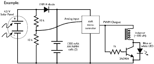
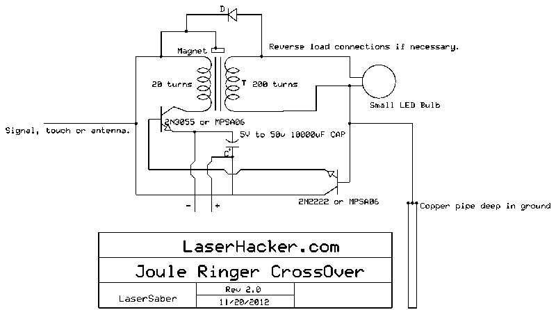
This example demonstrates the PWM (pulse-width modulation) output of a microcontroller controlling a Joule Thief style voltage booster to power a white LED. The circuit described utilizes a microcontroller to generate a PWM signal, which is an effective method for...
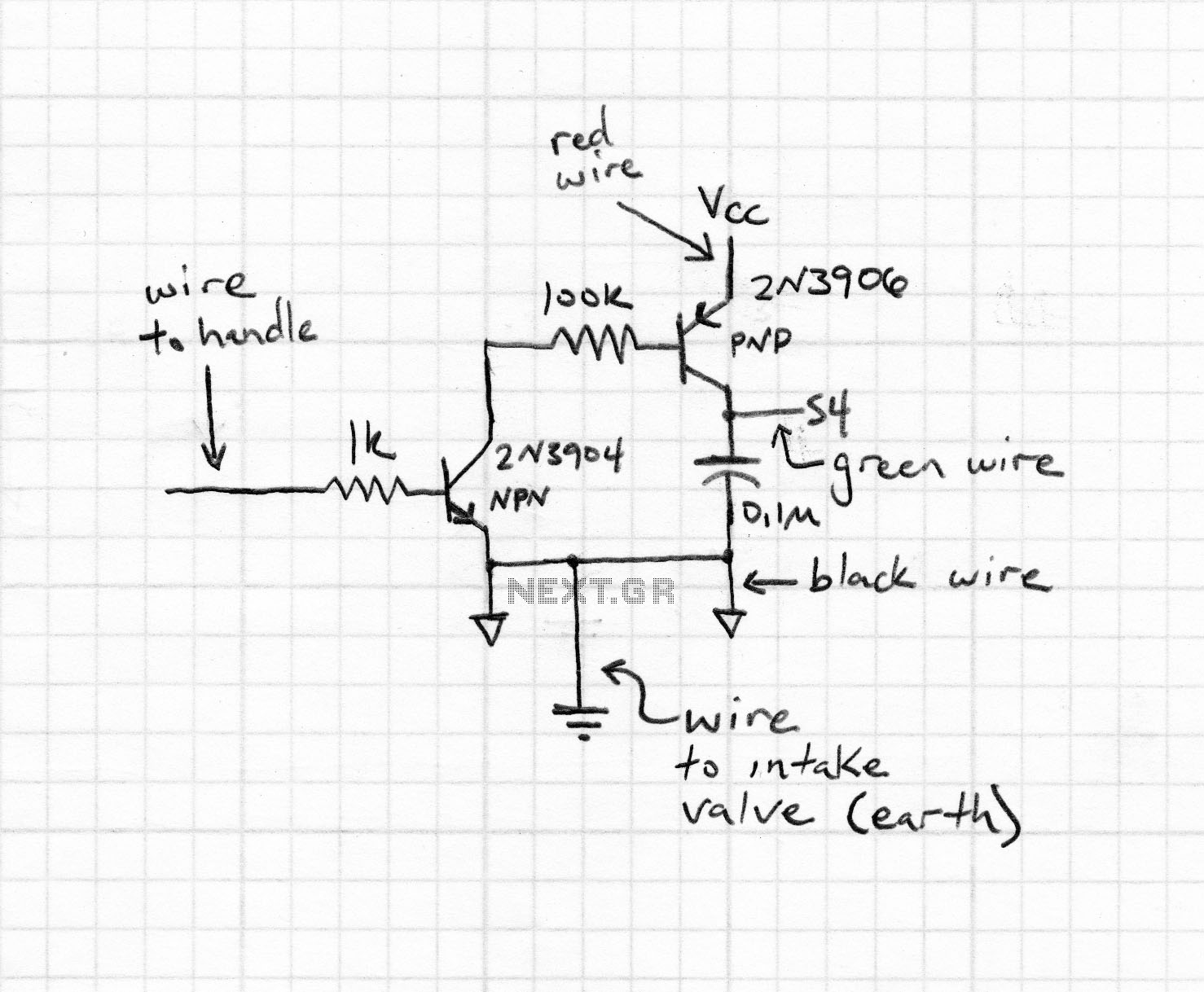
The conversion of a circuit from NPN to PNP configuration is in progress, along with a switch in polarity. Parts are being ordered for this modification. The conversion from an NPN to a PNP transistor involves several key changes in...
A typical device that requires less than 5v and draws less than 25mA is an LED. A LED must be supplied with an exact voltage for it to operate correctly. Because it requires LESS than 5v, a dropper resistor...
Upon entering the password, the application, in this case "LED," will illuminate. In this digital locking system project, the interfacing of a keypad and a 16x2 LCD with a microcontroller will be explored, along with the accompanying code. This...
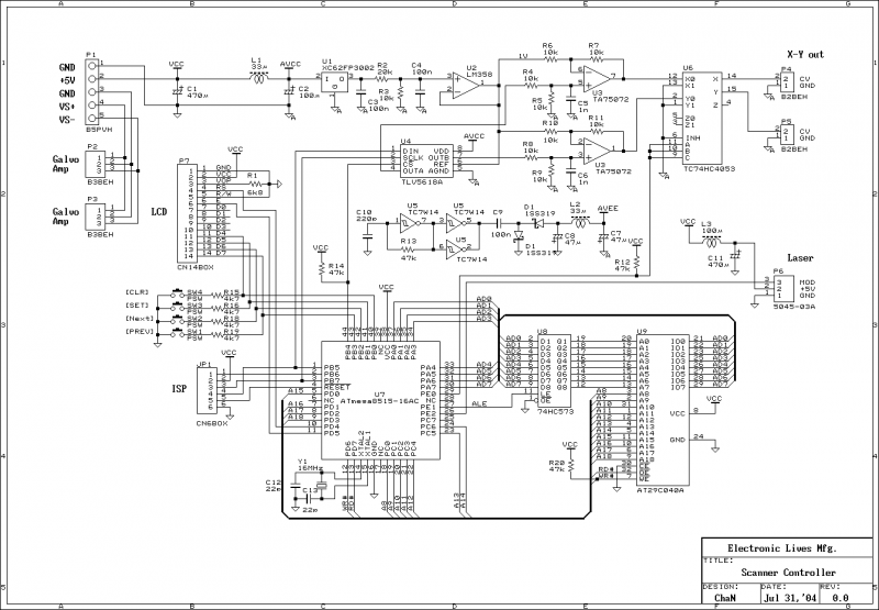
This document outlines the servo amplifier and its circuit diagram. It describes a straightforward operational amplifier circuit that integrates both a power amplifier and a small signal amplifier on the same board. Care must be taken to avoid unintended...
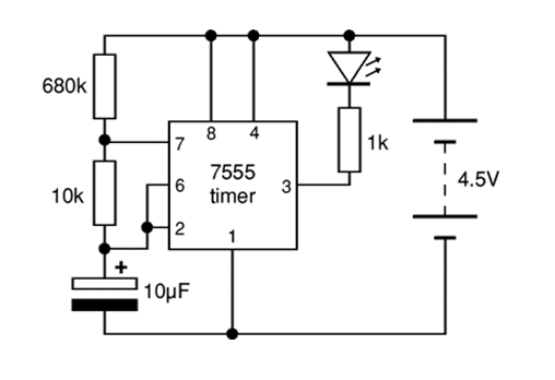
The 7555 timer IC used is a low power version of the standard 555 timer. A super bright red LED is utilized because it provides a bright flash with low current. The 7555 timer IC is a versatile low-power component...