
joule thief circuit project

The conversion from an NPN to a PNP transistor involves several key changes in the circuit design. NPN transistors are configured to conduct current when a positive voltage is applied to the base relative to the emitter, while PNP transistors require a negative voltage for the same effect. This fundamental difference necessitates a re-evaluation of the biasing and connection of components within the circuit.
In a typical NPN circuit, the collector is connected to a positive voltage supply, and the emitter is grounded. During conversion to a PNP configuration, the collector must be connected to a negative voltage supply, and the emitter should be connected to the positive voltage. The base resistor values may also need to be adjusted to ensure proper biasing of the PNP transistor, which typically involves changing the resistor values to accommodate the new voltage levels.
Additionally, any other components that interact with the transistor, such as diodes or capacitors, may require reconfiguration to maintain the desired functionality. It is crucial to ensure that the signal flow remains consistent with the original design's intent, despite the polarity and transistor type changes.
When ordering parts, it is advisable to select PNP transistors with similar specifications to the original NPN components, including current rating, voltage rating, and frequency response, to ensure compatibility and performance. Proper attention to these details will facilitate a successful transition to the PNP configuration while maintaining circuit integrity.I convert this to PNP from NPN entirely + switch polarity I am ordering parts. 🔗 External reference
Related Circuits
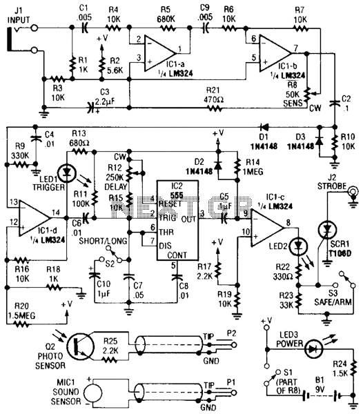
Sound or light sensors connected to J2 produce a voltage that is amplified by IC1-a and IC1-b. A positive trigger voltage developed by D1 and R3, and amplified by IC1-d, drives IC2 and IC1 to trigger SCR1. SCR1 is...
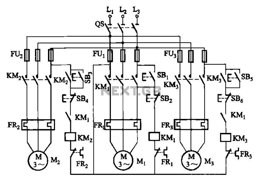
The circuit shown in Figure 3-89 illustrates a system where starting motor M1 allows motors M2 and M3 to initiate operation. Upon shutdown, motor Mz can be stopped first; however, once motor M1 is stopped (by pressing switch SB2),...
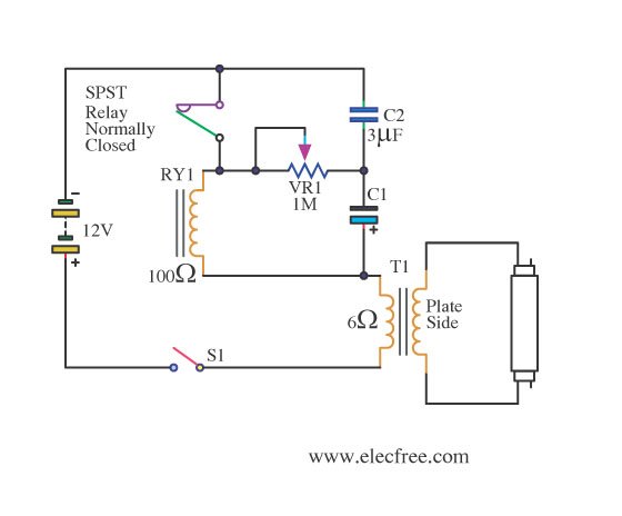
This is a flashing blink circuit designed for 12V applications. It utilizes a small-sized fluorescent lamp and operates through a relay that modifies the circuit from DC to AC. The flashing blink circuit operates at a voltage of 12V, making...
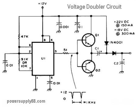
This circuit diagram represents a DC voltage doubler and DC converter. It is designed to convert a 12V DC power supply into outputs of 24V DC and 18V DC. Nearly any PNP or NPN power transistors can be utilized...
The objective of this project was to design a small portable mixer powered by a 9V PP3 battery while maintaining performance quality. The mixer consists of three main modules that can be varied in number and can be adapted...
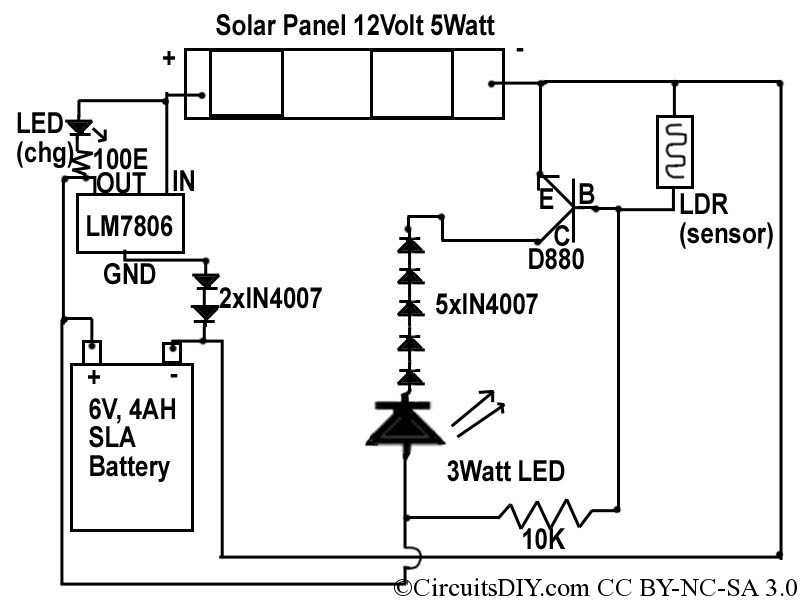
This document discusses a simple solar LED circuit. Solar panels range from 12 volts and 3 watts to larger sizes. To store energy, a 12-volt battery is required. The preferred choice is a sealed lead-acid (SLA) sealed maintenance-free (SMF)...